Waterproof connector

a technology of connectors and connectors, applied in the direction of couplings/cases, coupling device connections, securing/insulating coupling contact members, etc., can solve the problem of taking a lot of time and labor to perform the operation of mounting the sealing member, and achieve the effect of reducing the number of components and facilitating the operation of mounting

Inactive Publication Date: 2005-06-28
SUMITOMO WIRING SYST LTD
View PDF4 Cites 14 Cited by
  • Summary
  • Abstract
  • Description
  • Claims
  • Application Information

AI Technical Summary

Benefits of technology

[0008]The present invention has been made in view of the above-described situation. Thus, objects of the present invention are to enable an easy mounting of a sealing member on a female housing and provide a compact connector.
[0012]According to the present invention, the through-hole of the sealing member is closely fitted over the projected portion of the male terminal c when the female housing is fitted to the male housing. The sealing member is sandwiched between the front end surface of the female housing and that of the male housing. In the male housing, the inner peripheral surface of the through-hole of the sealing member closely contacts the peripheral surface of the sealing projection of the male terminal. In the female housing, the contact surface of the sealing member closely contacts (i.e., face contact) the front end surface of the female housing. In this way, waterproofing of the connector is accomplished.
[0013]Since the sealing member is installed on the exposed front end surface of the female housing, it is easy to install the sealing member into the connector.
[0014]In the sealing construction of the female housing, the sealing member makes face contact with the front end surface of the female housing. Thus, unlike the conventional case in which the inner peripheral surface of the sealing member contacts the peripheral surface of the terminal, it is unnecessary to provide the sealing member separately for each terminal or provide a space between adjacent terminals to insert a rib therebetween. Accordingly, it is possible to make the interval between the adjacent terminals short and to make the connector compact.
[0017]The sealing member is preferably formed integrally with the holder by two-color molding. In this way, the number of component parts can be reduced and the mounting operation can be performed easily.

Problems solved by technology

Thus, a connector with this conventional construction has a problem in that it takes much time and labor to perform the operation of mounting the sealing member 6 on the male housing 3.

Method used


Image

  • Waterproof connector
  • Waterproof connector
  • Waterproof connector

Examples


Embodiment Construction

[0033]An embodiment of the present invention is described below with reference to FIGS. 1 through 10.

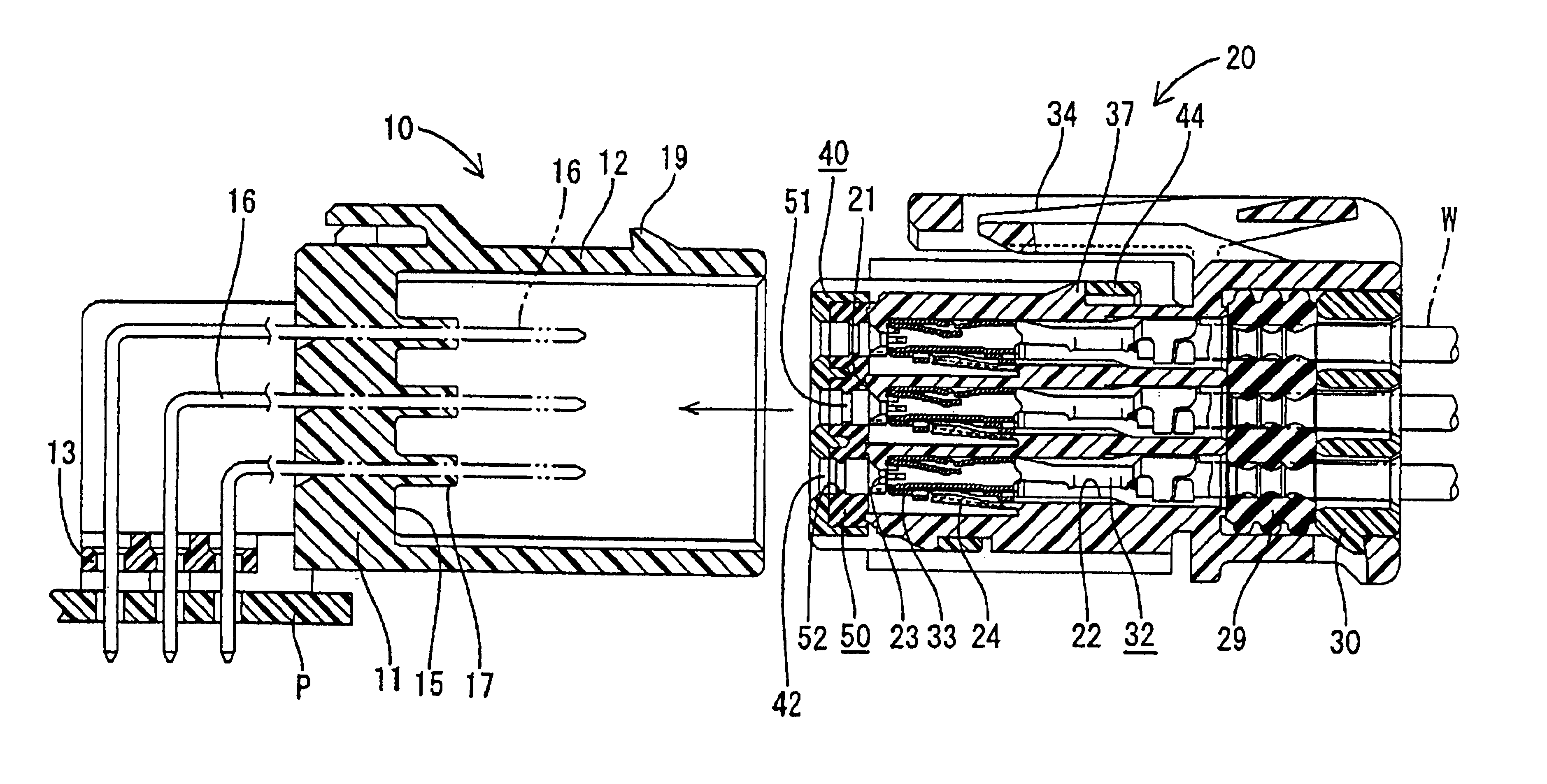
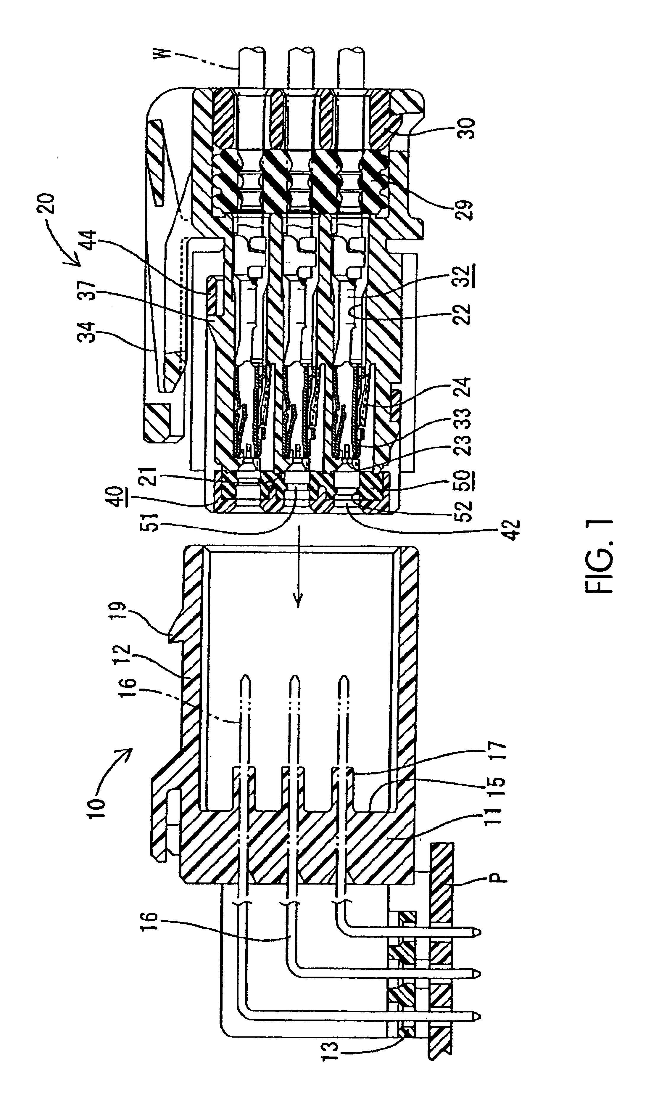
[0034]As shown in FIG. 1, the waterproof connector of the illustrated embodiment has a male housing 10, a female housing 20, and a sealing member 50 to be mounted on the female housing 20. In the description below, the sides of the male housing 10 and of the female housing 20 that connect to the opposing housing are each considered as the front or forward side.

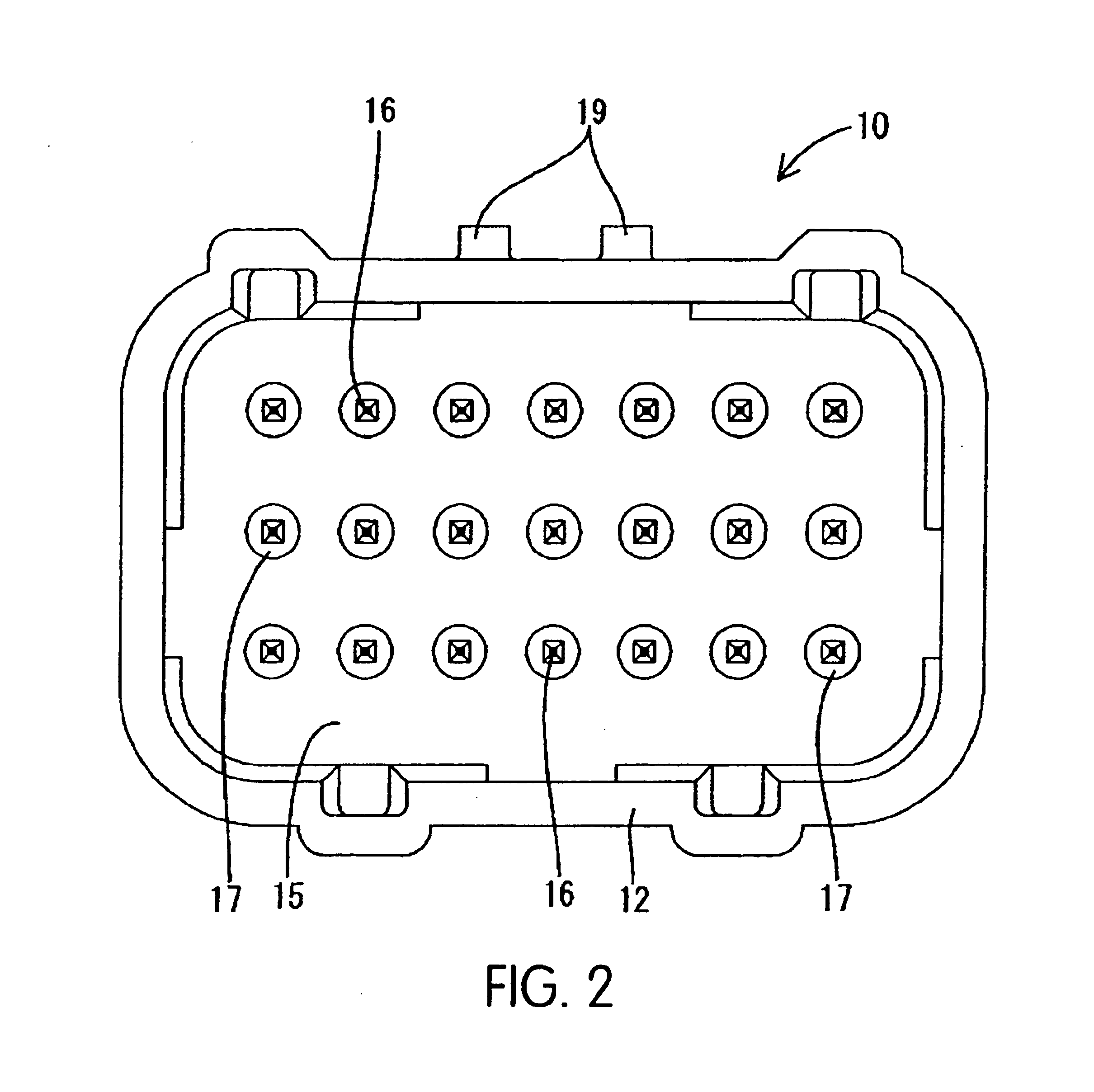
[0035]The male housing 10 is preferably of a substrate-installed type and made of a synthetic resinous material. A hood part 12 projects from a front surface of a body plate 11. A mounting plate 13 for a printed-circuit board P is formed at a lower portion of a rear surface of the body plate 11. The front surface of the body plate 11 serves as a front end surface 15 of the male housing 10.

[0036]L-shaped male terminals 16 are mounted inside the male housing 10 by insert molding. As shown in FIG. 2, the male terminals 16 are pref...


PUM


Abstract

On a front end surface of a male housing, a columnar sealing projection is formed for a projected portion of each of the male terminals. A sealing member having through-holes formed thereon is formed integrally with a rear surface of a front plate of a holder. When the holder is mounted on a female housing, a contact surface of the sealing member is pressed against the front end surface of the female housing. When the female housing is connected to the male housing, the inner peripheral surfaces of the through-holes of the sealing member closely contact the peripheral surfaces of the sealing projections with the sealing projections breaking the lips of the sealing member.

Description

BACKGROUND OF THE INVENTION[0001]1. Field of the Invention[0002]The present invention relates to a waterproof connector.[0003]2. Description of the Related Art[0004]A waterproof connector wherein the chamber containing the terminals is sealed is described in Japanese Patent Application No. 2001-267000. This waterproof connector is described below with reference to FIG. 11. The waterproof connector has a female housing 1 provided with a plurality of the cavities 1A for accommodating female terminals 2. The male housing 3 is designed for a printed-circuit board and includes a hood part 3A in which the female housing 1 can be fitted. L-type male terminals 4 project from the front end surface 3B into the hood part 3A. A mounting concavity 5 is formed around the projected portion of the male terminal 4 on the front end surface 3B of the male housing 3. A sealing member 6 is mounted in the mounting concavity 5.[0005]A press-fit groove 7 is formed around the opening 6A on the surface of th...

Claims


Application Information

Patent Timeline
Patent Type & Authority Patents(United States)
IPC IPC(8): H01R13/52
CPCH01R13/5208H01R13/521H01R13/5221
Inventor TANAKA, NOBUYOSHIICHIDA, KIYOFUMI
Owner SUMITOMO WIRING SYST LTD
Why Eureka
Try Eureka