
Pulper for producing paper pulp from waste paper

Inactive Publication Date: 2005-06-28
JLR PULPING SYST
View PDF2 Cites 0 Cited by
  • Summary
  • Abstract
  • Description
  • Claims
  • Application Information

AI Technical Summary

Benefits of technology

[0006]The object of the present invention is to provide a pulper that efficiently prevents disintegration of relatively large scrap particles and minimises the lost of fibres.
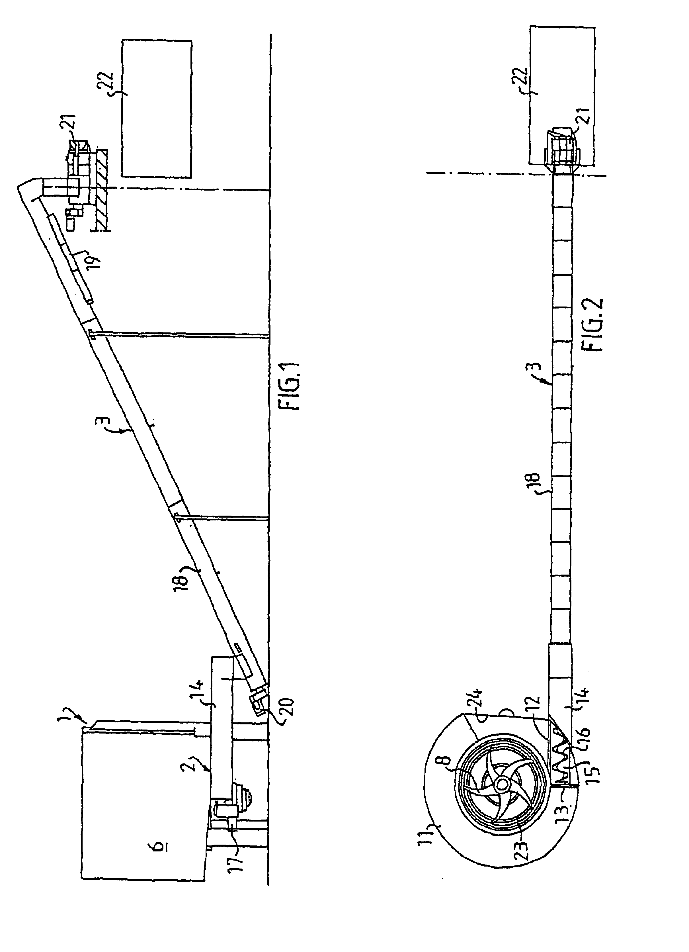
[0008]The conveyer screw has an inlet end and an outlet end, wherein the conveyer screw is journalled at the inlet end thereof in a manner such that it is radially moveable at its outlet end. The fact that the conveyor screw is coreless and radially moveable at its outlet end means that the discharged pipe is efficiently prevented from being clogged by long particles such as plastic shreds that rotate along with the conveyor screw. Suitably, a drive means is adapted to intermittently rotate the conveyor screw to discharge reject in batches from the reject chute.

Problems solved by technology

A problem of the traditional pulpers however is that also relatively large scrap particles are disintegrated by the rotating paper tearing member into smaller particles that are able to pass through the strainer of the pulper, which makes it more difficult to clean the primary paper pulp in the subsequent cleaning steps.
However, the known pulper is not capable of satisfactorily preventing large scrap particles from being disintegrated by the paper tearing member.
In addition, some released fibres are lost through the reject outlet, which is a drawback.

Method used


Image

  • Pulper for producing paper pulp from waste paper
  • Pulper for producing paper pulp from waste paper

Examples


Embodiment Construction

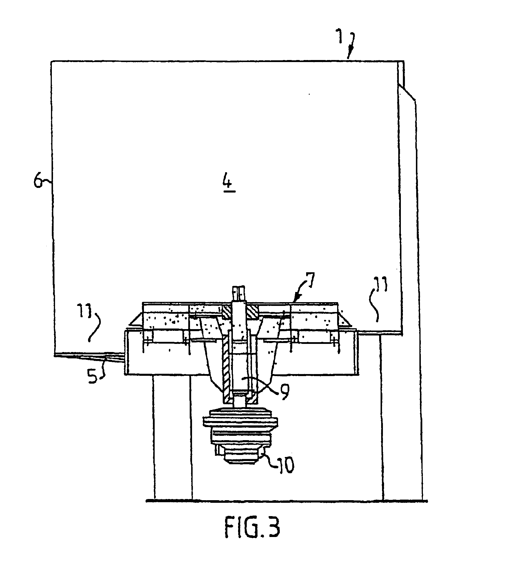
[0015]FIG. 1 shows a pulper according to the invention comprising a container 1 for receiving waste paper bales in batches, a discharge means 2 for discharging reject in batches from the container 1 and a dewatering means 3 for dewatering discharge reject. The container 1 forms a chamber 4 defined by a bottom wall 5 and a vertical cylindrical circumferential wall 6, see FIG. 3. The cylindrical circumferential wall 6 has a diameter of about 5 meter and comprises a plane wall portion 24, which forms a radial constriction in the chamber 4. A paper tearing member 7 with five knife blades 8 is attached to a vertical rotor shaft 9 journalled centrally on the bottom wall 5 and rotatable by a motor 10.

[0016]The bottom wall 5 and the cylindrical circumferential wall 6 form a circular peripheral reject chute 11 situated under the paper tearing member 7. The reject chute 11 extends helically in the direction of rotation of the paper tearing member 7 from an upper end 12 of the reject chute 11 ...


PUM

PropertyMeasurementUnit
Shapeaaaaaaaaaa

Abstract

A pulper for producing paper pulp from waste paper containing undesired scrap particles includes a container (1) forming a chamber (4) defined by a bottom wall (5) and a cylindrical circumferential wall (6). A paper tearing member (7) is arranged in the chamber closed to the bottom wall and is rotatable in a horizontal direction of rotation about the centre axis of the cylindrical wall. The bottom wall and the circumferential wall forms a substantially circular peripheral reject chute (11) situated under the paper tearing member for collecting reject including undesired scrap particles. The reject chute extends helically in the direction of rotation of the paper tearing member from an upper end (12) of the reject chute downwardly to a lower end (13) of the reject chute. The circumferential wall (6) has a substantially cylindrical shape and extends vertically to the reject chute (11). A discharge element (2) is adapted to discharge reject in batches from the reject chute.

Description

[0001]This application is a 371 of application PCT / SE01 / 00606 filed on 21 Mar. 2001.BACKGROUND OF THE INVENTION[0002]The present invention relates to a pulper for producing paper pulp from waste paper containing undesired scrap particles. The pulper comprises a container forming a chamber for receiving waste paper and water. The chamber is defined by a bottom wall and a substantially cylindrical circumferential wall. The pulper further comprises a paper tearing member provided in the chamber closed to the bottom wall and rotatable in a horizontal direction of rotation about the centre axis of the cylindrical wall. The bottom wall and the circumferential wall form a substantially circular peripheral reject chute situated under the paper tearing member for collecting reject including undesired scrap particles and extending helically in the direction of rotation of the paper tearing member from an upper end of the reject chute to a lower end of the reject chute, the circumferential wal...

Claims


Application Information

Patent Timeline
IPC IPC(8): D21B1/34D21B1/00
CPCD21B1/345
Inventor SELIN, ROLAND
Owner JLR PULPING SYST
Learn More