Electrochemical sensor

a technology of electrochemical sensors and capillaries, applied in the direction of diaphragms, packaged goods, immobilised enzymes, etc., can solve the problems of difficult to attach lids and control the path length, difficulty in repeatedly producing cavities of precise depth, and production of precision optical path lengths

Inactive Publication Date: 2005-06-28
ASCENSIA DIABETES CARE HLDG AG
View PDF5 Cites 112 Cited by
  • Summary
  • Abstract
  • Description
  • Claims
  • Application Information

AI Technical Summary

Problems solved by technology

A significant problem in the fabrication of optical reagent sensors is the production of a precision optical path length.
The precise depth of the cavity is difficult to produce repeatedly, but even if the depth can be repeatedly produced, it is very difficult to attach a lid and control the path length due to the tolerances of the method of attachment.
The difficulty in repeatedly producing a cavity of a precise depth is critical when producing an optical reagent sensor that is to be used in the transmission mode.
Similarly, the formation of a capillary channel in an injection molded sensor is difficult to produce.

Method used


Image

  • Electrochemical sensor
  • Electrochemical sensor
  • Electrochemical sensor

Examples


Embodiment Construction

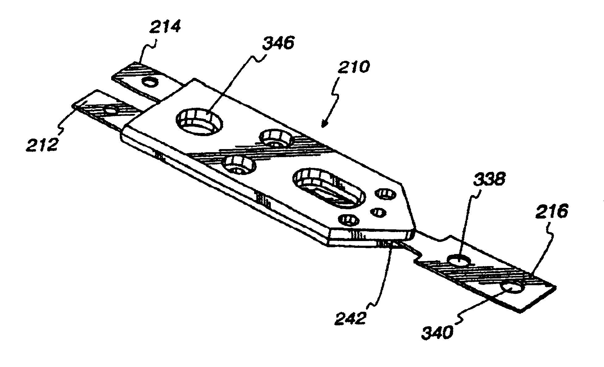
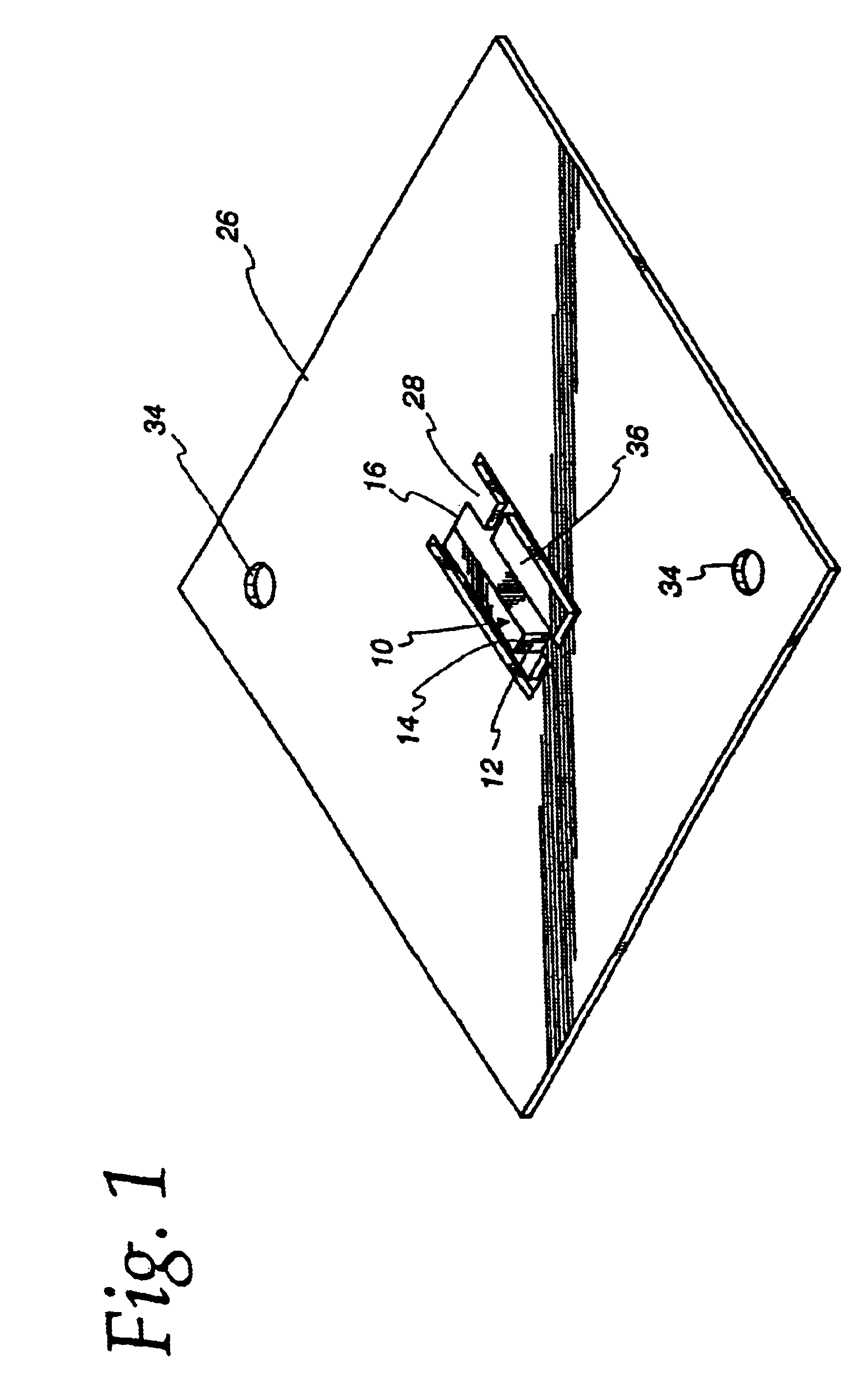
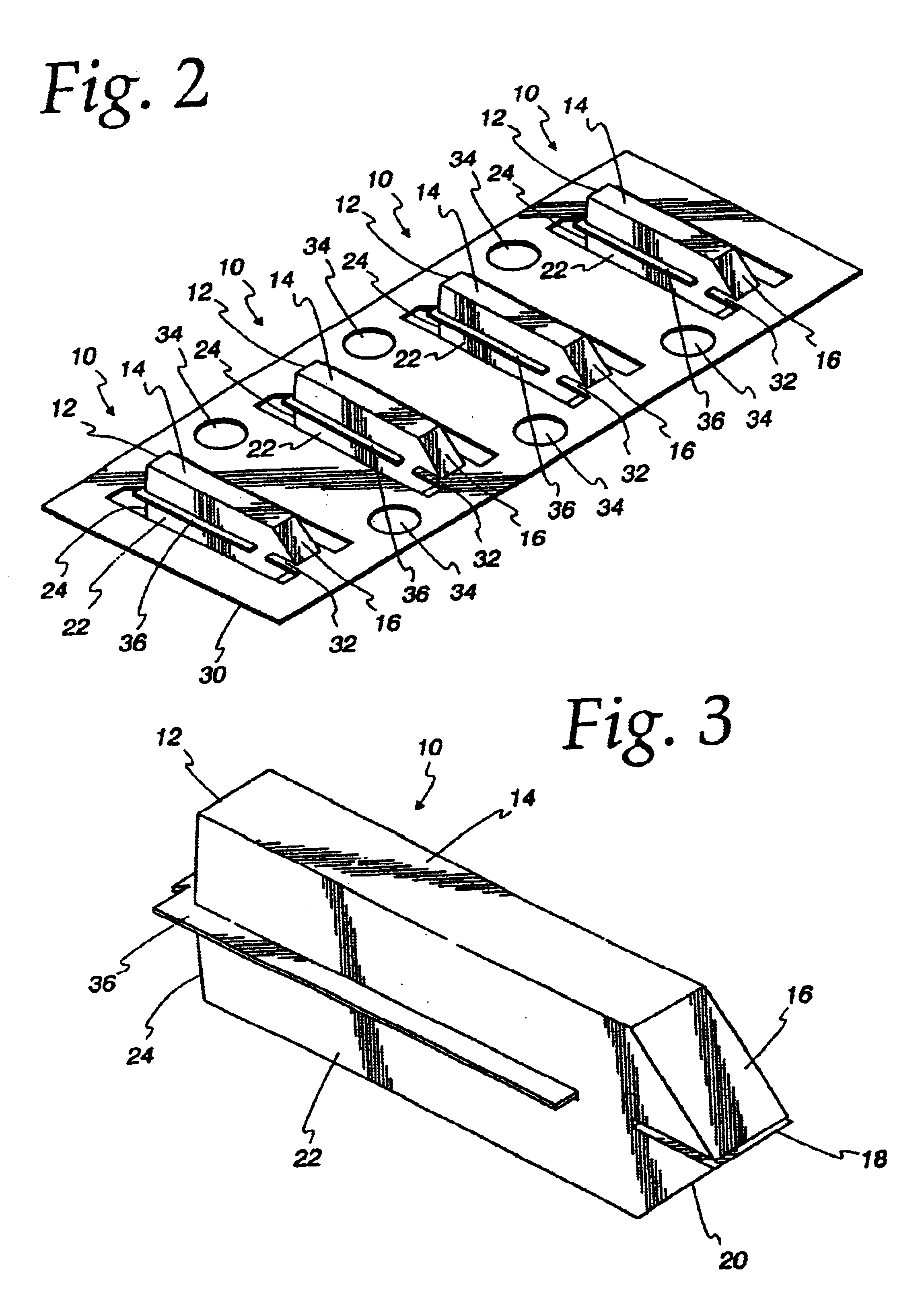
[0027]Referring to FIGS. 1-4, the sensor format 10 of the present invention is illustrated. The format 10 is an optical pipe formed of light transmission material. A light source is applied to an end 12 of a first leg 14 of the format 10. Light from the light source travels the length of the first leg 14 until it strikes a first end surface 16 that is at a 45° angle to the longitudinal axis of the first leg 14. The light is reflected by the end surface 16 through a capillary gap 18. Light that is not absorbed by material in the gap 18 strikes a second end surface 20 which is at a 45° to a longitudinal axis of a second leg 22 of the format 10. This light is reflected the length of the second leg 22 to a detector positioned at an end 24 of the second leg 22.

[0028]The format 10 is used in the transmission mode and the path length in the gap 18 is directly proportional to an analyte being tested. If the same analyte is measured in two different formats that have different path lengths, ...


PUM

PropertyMeasurementUnit
heightaaaaaaaaaa
melt temperatureaaaaaaaaaa
electric currentaaaaaaaaaa

Abstract

An optical reagent format with a precise capillary channel is made by molding a format on a carrier of a precise predetermined thickness. The carrier includes an insert at least a portion of which is molded in the format. Once the format is made, the insert is detached from the carrier and removed from the format leaving a precisely dimensioned capillary channel with an inlet and vent. A reagent may be applied in the capillary channel and the format used to measure the analyte in a fluid such as blood.An electrochemical sensor with a capillary channel is formed by placing a sacrificial insert and electrodes on a sensor base and applying plastic material. After the plastic material is cured, the sacrificial is removed leaving a capillary channel in the sensor. The inserts may be removed by a tool including a clamp for clamping and holding each insert stationary and a sliding block to which the sensor is secured.

Description

[0001]This application claims the benefit of provisional application 60 / 254,626, filed on Dec. 12, 2000.FIELD OF THE INVENTION[0002]The present invention relates to precision capillary channels for sensors and the method of making them.BACKGROUND OF THE INVENTION[0003]Sensors are used for sampling a fluid, mixing the fluid with a reagent, and making an analysis of the mixed sample. One form of sensor includes a capillary channel between two optical paths and a reagent in the channel. Another sensor is injection molded with a capillary channel between a base and lid. Electrodes and a reagent are located in the channel. A test fluid is drawn into the channel by capillary action and reacts with the reagent. In the first sensor, a light source is applied to one of the optical paths, and light from the light source is transmitted through the fluid in the channel and directed to a detector applied to the other optical path. In the second sensor an electric current acrossed the electrodes ...

Claims


Application Information

Patent Timeline
Patent Type & Authority Patents(United States)
IPC IPC(8): B01L3/00B29C45/14G01N27/447G01N27/403G01N21/03G01N1/00B01L9/00B01L99/00G01N37/00
CPCB29C45/14B29C45/14639B29C45/14754G01N21/03G01N27/4473B01L3/502707B01L3/5027G01N2021/0346B01L2200/12B01L2300/0645B01L2300/0809B01L2300/0825B01L2400/0406B29C45/14065B29C2045/1477
Inventor BRENNEMAN, ALLEN J.WOGOMAN, FRANK W.
Owner ASCENSIA DIABETES CARE HLDG AG
Why Eureka
Try Eureka