Multi-channel control methods for switched power converters

a power converter and multi-channel control technology, applied in the direction of pulse technique, pulse counter, counting chain synchronous pulse counter, etc., can solve the problems of difficult scaling and integration of power supplies into integrated circuits, high cost of power supplies, so as to avoid cross channel interference or minimize the effect of interferen

Inactive Publication Date: 2005-06-28
EXAR CORP
View PDF10 Cites 42 Cited by
  • Summary
  • Abstract
  • Description
  • Claims
  • Application Information

AI Technical Summary

Benefits of technology

[0005]A multi-channel switched power converter in accordance with the invention has a reference count generator that generates a reference count signal that is commonly distributed to multiple, pulse with modulating (PWM) channels of the converter. The common reference count signal counts through a sequence of successive timing values. Events in each channel are scheduled relative to the common reference count. Examples of such events include the application or de-application of a driving voltage pulse to an inductive means of the channel and the taking of voltage and current measurement samples. Cross channel interference is avoided or minimized by scheduling or re-scheduling events in each active channel so that they do not occur simultaneously in potentially-interfering channels, for example the taking of a current measurement sample in one channel and the turning of an inductance-driving voltage pulse in a second channel.

Problems solved by technology

Such switching power supplies are quite complex and use numerous components to provide a number of precisely regulated output voltages to power the various integrated circuits and other components contained within the product being powered.
Relative to the cost and the quality of the products in which they are used, such power supplies are expensive, bulky and inefficient.
Such a power supply is difficult to scale and integrate into an integrated circuit and is typically fabricated using dedicated analog process technologies at captive semiconductor foundries.

Method used


Image

  • Multi-channel control methods for switched power converters
  • Multi-channel control methods for switched power converters
  • Multi-channel control methods for switched power converters

Examples


first embodiment

Section 1.1.1 First Embodiment of PWM Timing Generator

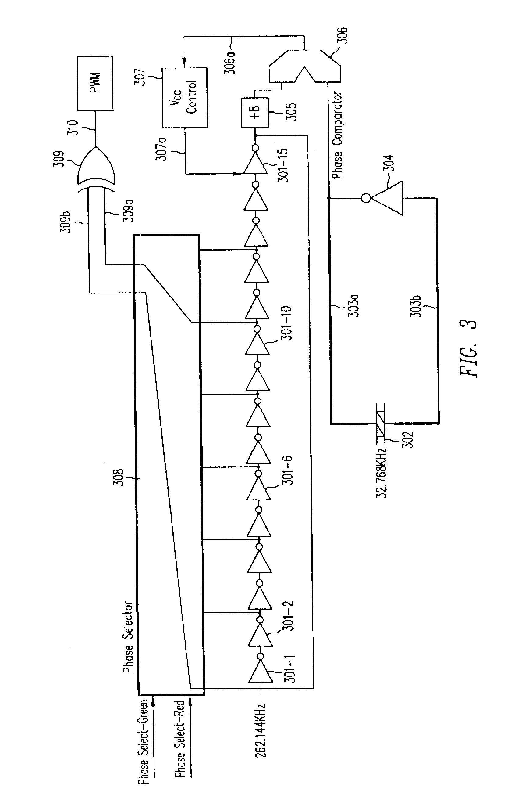
[0183]FIG. 3 shows a supply management controller of a type in accordance with this invention. As shown in FIG. 3, a ring oscillator includes inverters 301-1 through 301-15 connected in series. In an actual embodiment of this invention, the ring oscillator may include a larger number of series-connected inverters. For example, a thousand inverters can be connected in series, with the result that the duty cycle achieved by the controller of this invention can be almost 100%. However, to simplify explanation, only 15 inverters will be illustrated in this detailed description. The inverters each have inherently a delay “Δ,” which is the elapsed time between the time a signal is applied to the input lead to the inverter and the time the resulting output signal is obtained on the output lead of each inverter. This time “Δ” is a function of the voltage applied to the components contained within the inverter. By varying the voltage appl...

second embodiment

Section 1.1.2 Second Embodiment of the PWM Timing Generator

[0190]FIG. 4 shows an alternative embodiment of the invention employing counters and comparators to generate a pulse width modulated signal. A five bit counter 41 (although a different number of bits can be used if desired) counts from 0 to 31 driven by a 16.7772 MHz signal. The instantaneous count from 5 bit counter 41 is sent on 5-bit bus 42 to comparators 43a and 43b, each of which compares the count to a reference count stored in it. Digital comparator 43a will store one count determined by the signals on phase select bus 44a and digital comparator 43b will store a second count determined by the signals on phase select bus 44b. The signals on phase select bus 44a and phase select bus 44b are determined by external circuitry which measures the voltage on the load capacitor and the current into the load capacitor and compares the voltage and current to reference values to determine the extent to which the charge on the loa...


PUM


Abstract

Cross-channel interference can be a problem in multi-channel switched power systems. A multi-channel switched power converter is provided a reference count generator that generates a reference count signal that is commonly distributed to multiple, pulse width modulating (PWM) channels of the converter. The common reference count signal counts through a sequence of successive timing values. Events in each channel are scheduled relative to the common reference count. Examples of such events include the amplification or de-application of a driving voltage pulse to an inductive means of the channel and the taking of voltage and current measurement samples. Cross channel interference is avoided or minimized by scheduling or re-scheduling events in each active channel so that they do not occur simultaneously in potentially-interfering channels, for example the taking of a current measurement sample in one channel and the turning on of an inductance-driving voltage pulse is a second channel.

Description

FIELD OF THE INVENTION[0001]This invention relates to switching power supplies or converters. In particular, this invention relates to a simple, robust switching power supply which is capable of providing power to a number of different regulated power sources within a given circuit.BACKGROUND OF THE INVENTION[0002]Switching power supplies are used to provide power in numerous products such as cell phones, camera, PDAs (Personal Digital Assistants), calculators, portable computers and similar types of electronic equipment. Such switching power supplies are quite complex and use numerous components to provide a number of precisely regulated output voltages to power the various integrated circuits and other components contained within the product being powered. Relative to the cost and the quality of the products in which they are used, such power supplies are expensive, bulky and inefficient. Efficiency is important to provide the equipment a long battery life. FIG. 1 shows a typical ...

Claims


Application Information

Patent Timeline
Patent Type & Authority Patents(United States)
IPC IPC(8): H03K19/21H03K19/096H03K23/00H03K23/40H03K19/20
CPCH03K19/0963H03K23/40H03K23/005H03K19/215G05F1/40H02M3/157H02M1/0845
Inventor KERNAHAN, KENTTHOMAS, JOHN CARL
Owner EXAR CORP
Why Eureka
Try Eureka