Load-regulating device for scroll type compressors

a compressor and load regulation technology, applied in machines/engines, liquid fuel engines, positive displacement liquid engines, etc., can solve problems such as leakage and failure of building up pressure, affecting compressor reliability, and block not being able to overcome, so as to improve the performance and reliability of compressors

Inactive Publication Date: 2005-07-05
IND TECH RES INST
View PDF14 Cites 57 Cited by
  • Summary
  • Abstract
  • Description
  • Claims
  • Application Information

AI Technical Summary

Benefits of technology

[0007]The primary object of the present invention is to provide a load-regulating device for scroll type compressors, wherein the pressure variation in the air chambers is utilized for causing the motion of the gliding block, thus enabling the compressor to cause the gliding block by means of the pressure variation to motion upwardly at the actuation of the compressor, and preventing the fluid in the high-pressure chamber from leaking towards the low-pressure chamber, consequently allowing the compressor to quickly build up pressure, and then the gliding block is caused by the pressure variation to motion downwardly at times when the compression ratio is excessively high, so as to relieve a portion of the load.
[0011]The present invention is hereby presented for providing a load-regulating device for scroll type compressors applying the coupling of a gliding block and scrolls, wherein the gliding block is coupled with the pair of scrolls for defining a plurality of air chambers on the scrolls, the pressure variation in the air chambers is then utilized to cause the motion of the gliding block, thus enabling the compressor to cause the gliding block by means of the pressure variation to motion upwardly as the compressor is actuated, and preventing the fluid in the high-pressure chamber from leaking towards the low-pressure chamber, thus allowing the compressors to quickly build up pressure; the gliding block is caused by the pressure variation to motion downwardly at times when the compression ratio is excessively high to relieve a portion of the load, so as to improve the performance and reliability of the compressors, and eliminate the deficiency of the prior art in effective manner.

Problems solved by technology

However, the drawback of such a framework is that the amount of force present for the gliding block to solely motion upwardly is almost close to zero at time of actuation of the compressor or at times when the compression ratio is too low, thus making the gliding block unable to overcome the friction and weight and motion upwardly, resulting in leakage and failure of building up pressure.
Therefore, requiring additional force of the spring element to cause the gliding block to motion upwardly; at times when the compression ratio is excessively high, with the force imposed on the gliding block plus the upwardly-thrusting force of the spring element, the gliding block is forced not to be able to motion downwardly to relieve part of the load, thus affecting the reliability of the compressor.

Method used


Image

  • Load-regulating device for scroll type compressors
  • Load-regulating device for scroll type compressors
  • Load-regulating device for scroll type compressors

Examples


Embodiment Construction

[0018]The following is a detailed description of the best presently known modes of carrying out the inventions. This description is not to be taken in a limiting sense, but is made merely for the purpose of illustrating the general principles of the inventions.

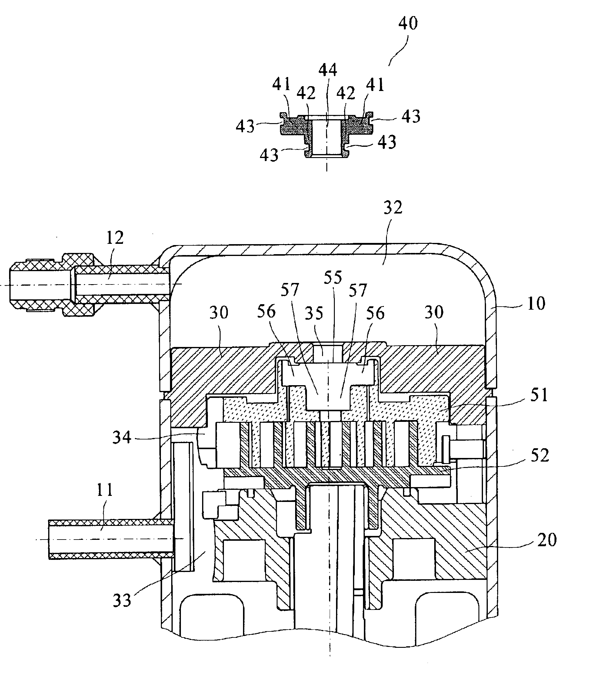
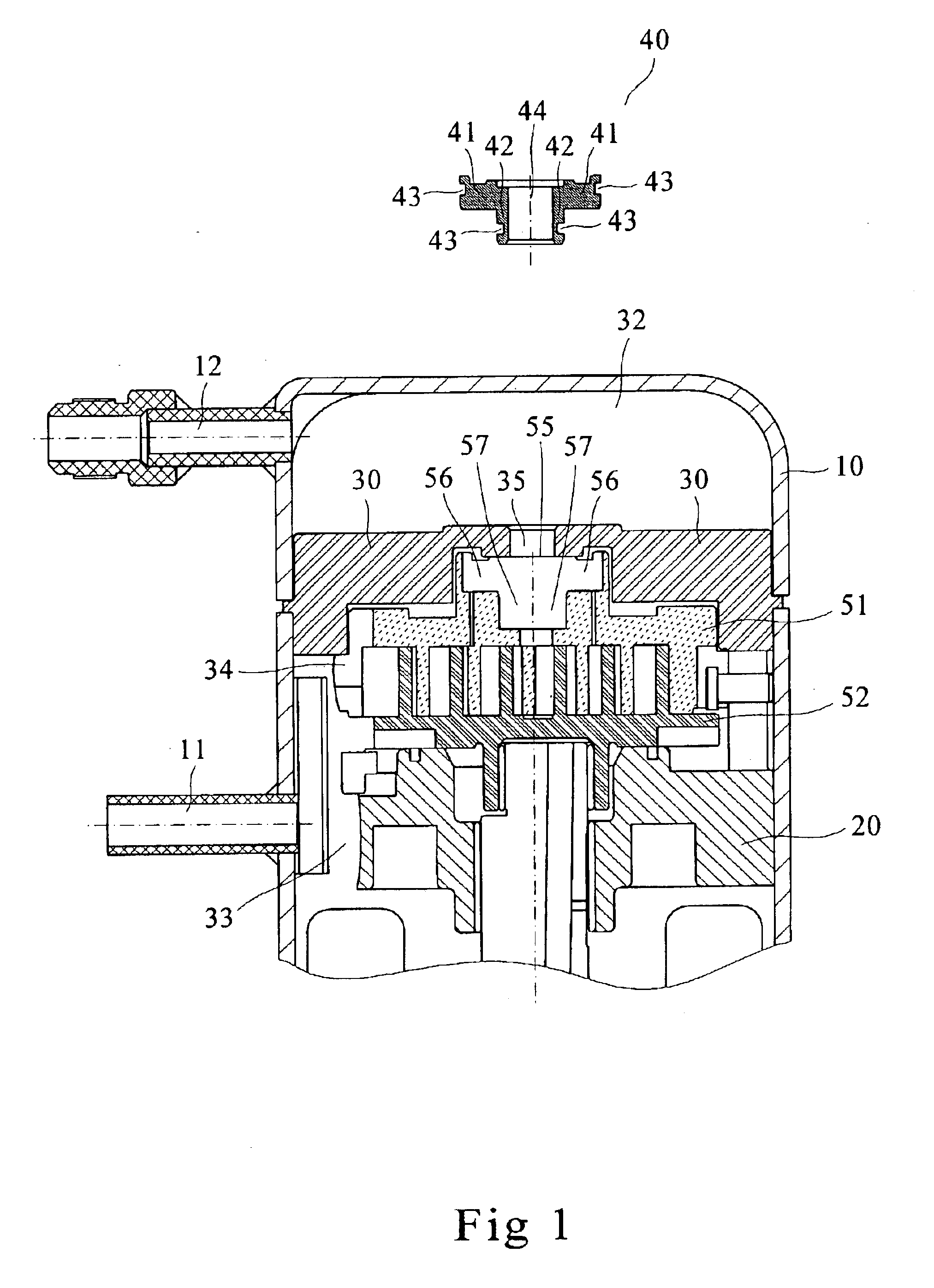
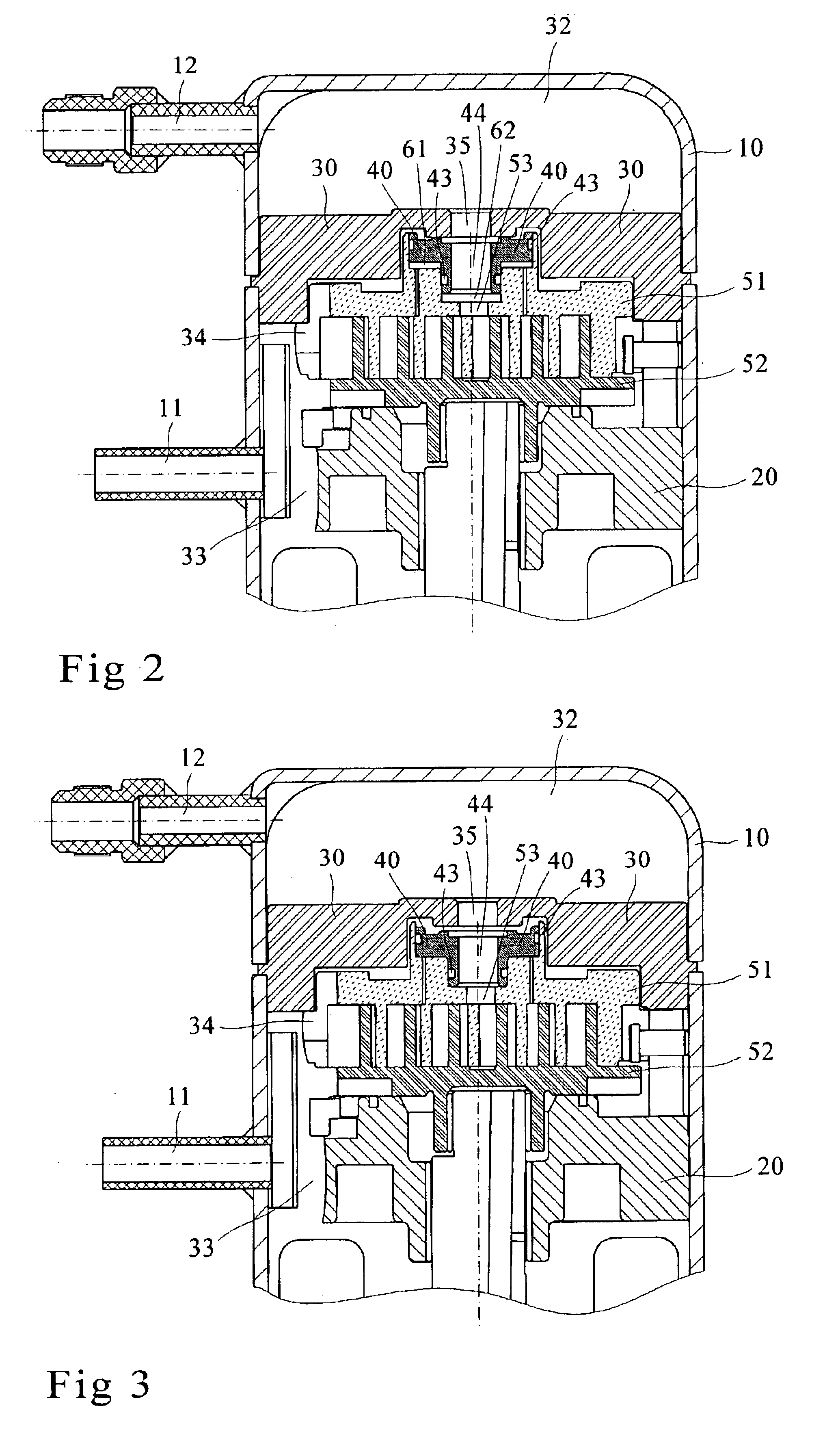
[0019]Please refer to FIG. 1, which shows the vertically sectional, dissected and structural view of the load-regulating device for scroll type compressors of the present invention, the device of the present invention comprises a compressor housing 10, a bracket body 20, a partition block 30, a gliding block 40, a pair of scrolls and a plurality of air chambers, wherein the compressor housing 10 containing an air supply inlet 11 and an air exhaust outlet 12; the bracket body 20 being fixed inside the compressor housing 10 and defining with the compressor housing 10 a chamber; the partition block 30, being fixed inside the compressor housing 10 and located on top of the bracket body 20 to divide the chamber into a high-pressure...


PUM


Abstract

A load-regulating device for scroll type compressors comprising a compressor housing, a bracket body, a partition block, a gliding block, a pair of scrolls and a plurality of air chambers, wherein the gliding block being coupled with the pair of scrolls for defining a plurality of air chambers on the scrolls, the pressure variation in the air chambers is then utilized for causing the motion of the gliding block, enabling the compressor to cause the gliding block by means of the pressure variation to motion upwardly as the compressor is actuated, and preventing the fluid in the high-pressure chamber from leaking towards the low-pressure chamber, thus allowing the compressors to quickly build up the pressure; the gliding block is caused by the pressure variation to motion downwardly at times when the compression ratio is excessively high, so as to relieve part of the load, thus improving the performance and reliability of the compressors.

Description

BACKGROUND OF THE INVENTION[0001]1. Field of the Invention[0002]The present invention refers to a load-regulating device for scroll type compressors, particularly the rendering of a gliding block coupled with a pair of scrolls for defining a plurality of air chambers on the scrolls, so as to cause the motion of the gliding block by means of the pressure variation in the air chambers.[0003]2. Description of Related Art[0004]The design for general compressors must provide the functions of preventing fluid from flowing backwards and building up pressure quickly as the compressors are actuated, and the excessively high pressure should be prevented from being accumulated so that the scrolls will not be damaged.[0005]A prior art as revealed in U.S. Pat. No. 6,059,549 shows an improved high-low-pressure sealing structure of scroll type compressors, whereby a gliding block is coupled with scrolls to form a single air chamber on the scrolls. As the compressor is actuated, the gliding block i...

Claims


Application Information

Patent Timeline
Patent Type & Authority Patents(United States)
IPC IPC(8): F04C27/00F04C18/02F04C28/26
CPCF04C27/005F04C18/0215
Inventor LIANG, KUN-ICHANG, YU-CHOUNGLAI, CHING-FENGHUANG, ANN-
Owner IND TECH RES INST
Why Eureka
Try Eureka