Coolant system

a cooling system and cooling chamber technology, applied in the direction of liquid cooling, coolant flow control, control devices of cooling apparatus, etc., can solve the problems of undesired release of air and coolant to the ambient atmosphere, etc., to avoid cavitation in the pump, prevent cavitation, and quickly build up pressure

Active Publication Date: 2011-11-29
VOLVO LASTVAGNAR AB
View PDF11 Cites 11 Cited by
  • Summary
  • Abstract
  • Description
  • Claims
  • Application Information

AI Technical Summary

Benefits of technology

[0007]During operating conditions when the temperature of the coolant is reduced, for example due to lower engine load or the cooling fan starting to engage, the coolant volume decreases and the pressure at the pump will be lowered. This will in turn reduce the pressure of the air in the expansion tank. When this pressure drops below a lower setting of the valve the valve opens, letting ambient air into the tank. This prevents the pressure in the cooling circuit from dropping below a predetermined pressure where cavitation may occur in the coolant pump.
[0032]The pressurized cooling systems described in the above embodiments provide a cooling system that can be controlled to quickly build up pressure at the coolant pump suction side when starting the engine, in order to avoid cavitation in the pump. The pressurized cooling systems according to the invention also provides means for maintaining an even pressure that is high enough to avoid pump cavitation during operation of the engine, even when the coolant has cooled down. The cooling systems also make it possible to avoid pressure peaks (high and low pressure) and pressure cycling that may damage the components in the coolant system. It is also desirable to avoid introducing ambient air into the system, which air may oxidize the coolant (ageing of coolant), and to avoid loosing coolant to ambient air. The invention will therefore have a positive effect on the life time of the components in the coolant system and of the coolant and the efficiency of the coolant pump. Examples of additional advantages with the solutions according to the invention are that coolant top off intervals should be less frequent since there is no continuous loss of coolant, which is also beneficial for the environment. Since the expansion tank has a larger expansion volume which is less sensitive to small leaks. With the expansion tank mounted on the chassis, the tank is easier to service and facilitates reading of the coolant level.

Problems solved by technology

Such systems require big air volumes or sufficiently small coolant volumes.
In a standard size tank, excess pressure spikes may cause a safety valve to open, which in turn would result in an undesired release of air and coolant to the ambient atmosphere.
The valve should only open when there is a risk of damaging components in the cooling system.
In a standard size tank, excess pressure spikes may cause a safety valve to open, which in turn would result in an undesired release of air and coolant to the ambient atmosphere.
The valve should only open when there is a risk of damaging components in the cooling system.

Method used


Image

  • Coolant system
  • Coolant system
  • Coolant system

Examples


first embodiment

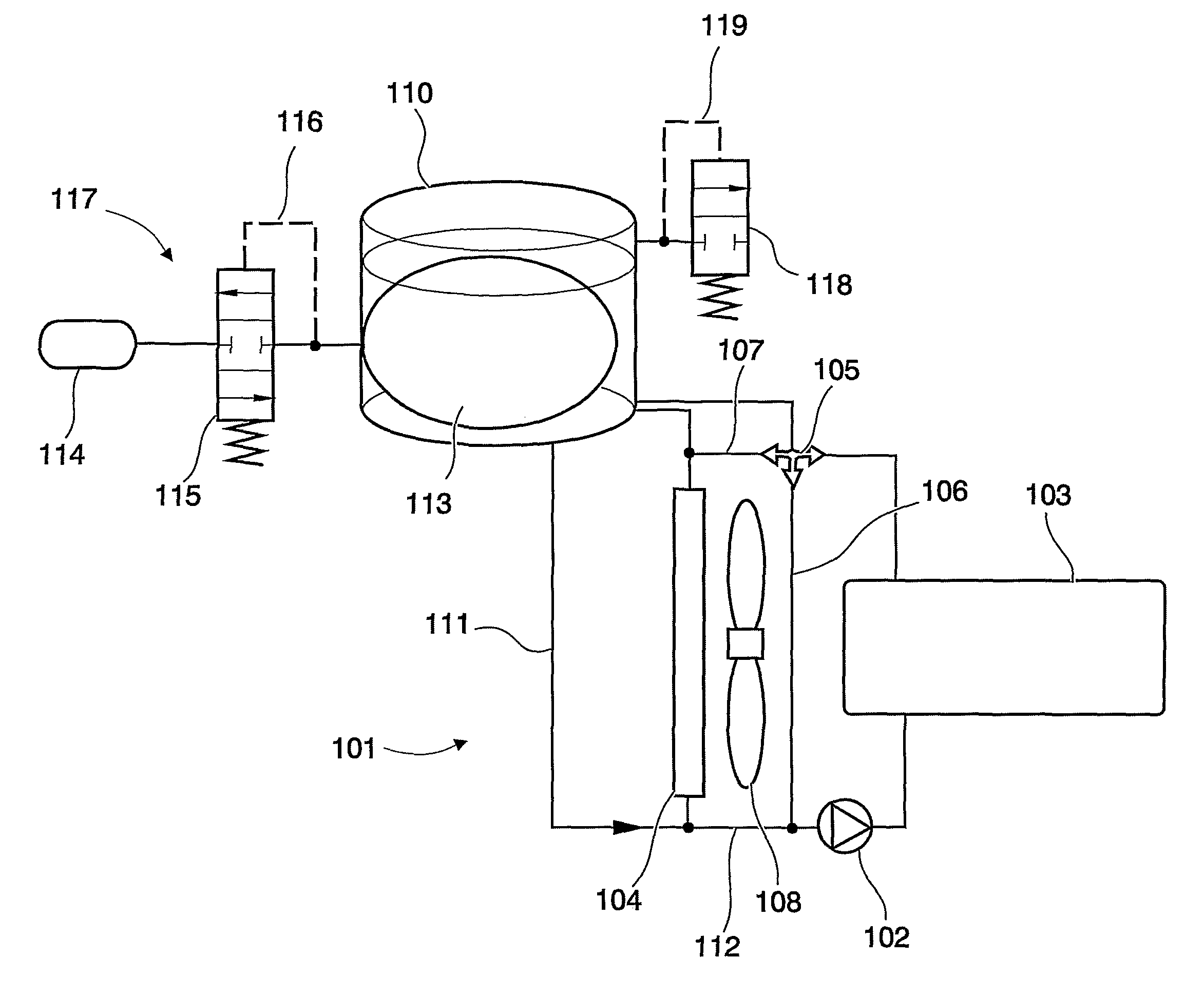
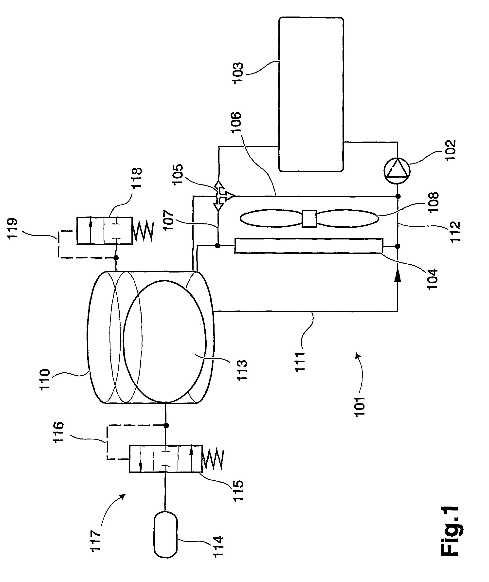
[0037]FIG. 1 shows a pressurized cooling system according to the invention.

[0038]The engine cooling system comprises a cooling circuit 101 with a coolant pump 102 for supplying an engine 103 with a coolant and for circulating the coolant in the cooling circuit 101. A radiator 104 is provided for cooling said coolant downstream of the engine 103. In the cooling circuit, the pump 102 will supply coolant to the engine 103, wherein the coolant is heated. Heated coolant will pass through a thermostat 105 which, depending on the temperature of the coolant, will direct the coolant directly back to the pump 102 through a first conduit 106, or indirectly via the radiator 104 through a second conduit 107. The radiator 104 is arranged to reduce the temperature of the coolant to a desired level, which temperature reduction is assisted by a cooling fan 108. The cooling system can also be arranged to cool a charge air cooler (not shown) located adjacent the radiator 104. An expansion tank 110 is ...

second embodiment

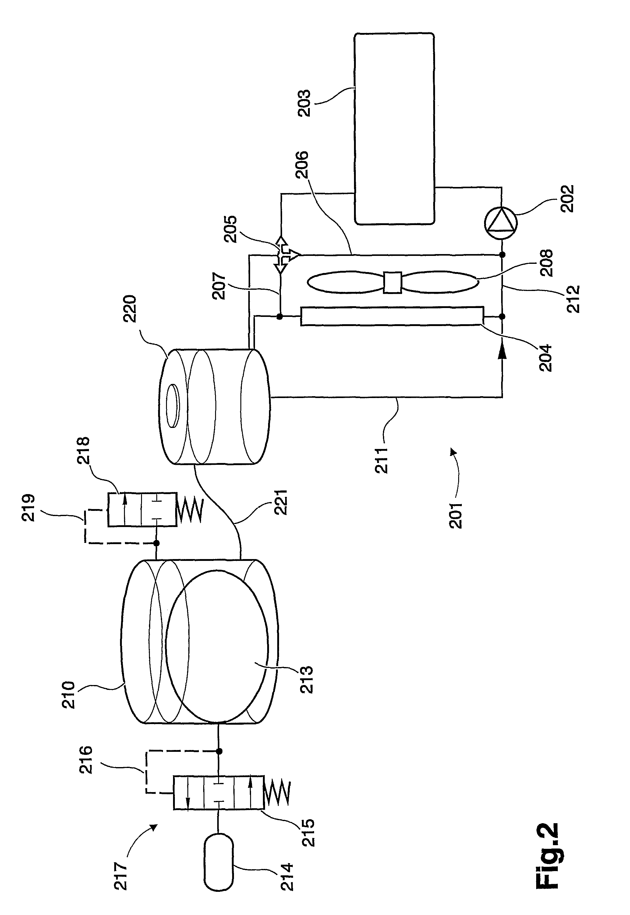
[0048]The expansion tank 210 is further provided with a safety valve 218. The safety valve 218 is set to release a relatively high excess pressure to the atmosphere. The safety valve 28 release pressure is preferably set at a level that will maintain the cooling system in a closed state during all normal operating conditions. The safety valve 218 should only open when there is a risk of damaging components in the cooling system. The safety valve 218 is a pressure controlled 2-way valve. The safety valve 218 is connected to an upper section of the expansion tank and is normally maintained in a closed position, as shown in FIG. 2. At a predetermined set pressure in a pilot conduit 219 acting on one end of the safety valve 218, the safety valve is opened to release excess pressure from the expansion tank 210. FIG. 3 shows a pressurized cooling system according to the invention. As in the embodiment of FIG. 2, the engine cooling system comprises a cooling circuit 301 with a coolant pump...


PUM


Abstract

An engine cooling system is provided with a cooling circuit including a coolant pump for supplying an engine with a coolant and for circulating the coolant in the cooling circuit, and at least one heat exchanger for cooling said coolant downstream of the engine, wherein an expansion tank is connected to the cooling circuit upstream of the coolant pump. The cooling system is pressurized by a pressure regulating arrangement arranged to pressurize coolant supplied to the cooling circuit from the expansion tank during at least one predetermined operating mode of the engine and the expansion tank is closed to the ambient atmosphere during all normal engine operation modes.

Description

BACKGROUND AND SUMMARY[0001]This invention relates to engine cooling systems for vehicles, such as trucks, cars or buses, as well as stationary generator units, in particular to cooling systems provided with an expansion tank closed to the ambient atmosphere.[0002]Engine cooling systems of this type often comprise an expansion tank. The expansion tank has many functions, among them to take care of the coolant expansion caused by increased coolant temperature, and to build up pressure in the system in order to pressurize the coolant pump suction side to avoid pump cavitation. For a truck or stationary engine installation with a coolant system containing 50-70 liters the coolant may expand around 2 liters from cold start to normal working temperature.[0003]With expansion tanks used in vehicles today, a common solution is to use a controllable valve that may be set to open at a predetermined, relatively high pressure. The valve links the expansion volume inside the expansion tank with ...

Claims


Application Information

Patent Timeline
Patent Type & Authority Patents(United States)
IPC IPC(8): F01P11/20
CPCF01P11/028F01P11/029F01P11/18F01P2037/02F01P2025/04F01P3/2207
Inventor DAHL, ERIKJEMT, KATARINA
Owner VOLVO LASTVAGNAR AB
Why Eureka
Try Eureka