Enhanced visual signaling for an adverse condition detector

a visual signal and detector technology, applied in the field of adverse condition detectors, can solve the problems of inability to immediately associate the visual signal being generated with the visual signal, the user of the adverse condition detector must know and be able, and the inability to remember and distinguish the two different audible alarm patterns. the effect of quick determination

Inactive Publication Date: 2005-07-05
MAPLE CHASE
View PDF3 Cites 23 Cited by
  • Summary
  • Abstract
  • Description
  • Claims
  • Application Information

AI Technical Summary

Benefits of technology

[0011]During generation of the audible alarm signal, the control unit generates a visual alarm signal that indicates to the user the type of alarm condition being detected. In accordance with the present invention, the visual alarm signal visually simulates the type of adverse condition triggering the alarm such that the user can quickly and easily determine the type of adverse condition being detected.
[0017]The generation of the visual alarm signal by the microprocessor control unit allows a user to visually examine the adverse condition detector during the generation of an alarm signal and quickly determine the type of adverse condition being detected. The generation of the visual alarm signal in accordance with the present invention does not require the user to have any knowledge of the audible alarm patterns or speak a specific language in order to determine the type of adverse condition being detected.

Problems solved by technology

However, a limitation exists in that the user of the adverse condition detector must know and be able to distinguish the two types of audible alarms generated by the single adverse condition detector.
Since many users only hear the two different audible patterns during a manual test of the detector, these users are unable to remember and distinguish the two different audible alarm patterns during an alarm situation.
Therefore, if the alarm signals are being generated in a dark building, it is difficult for the user to immediately associate the visual signal being generated with one of the types of adverse conditions being sensed.
Although this type of alarm system works well with a user that understands English, a non-English speaking user would be unable to distinguish the types of alarms being generated.

Method used


Image

  • Enhanced visual signaling for an adverse condition detector
  • Enhanced visual signaling for an adverse condition detector
  • Enhanced visual signaling for an adverse condition detector

Examples


Embodiment Construction

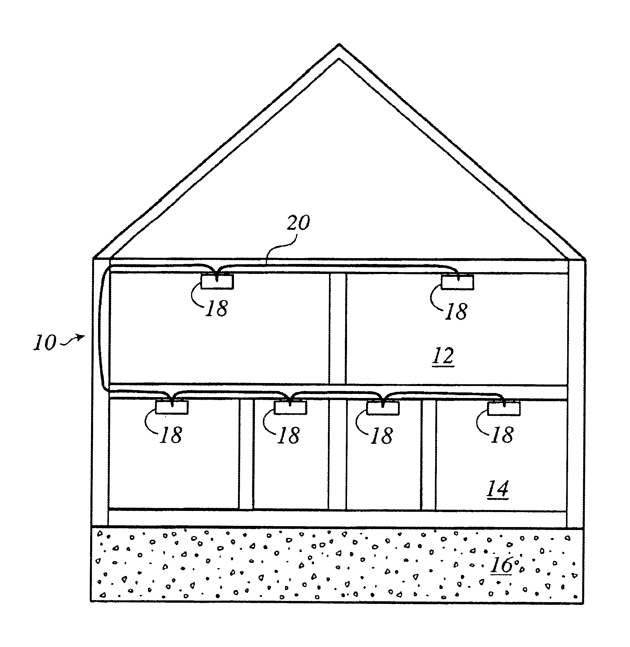
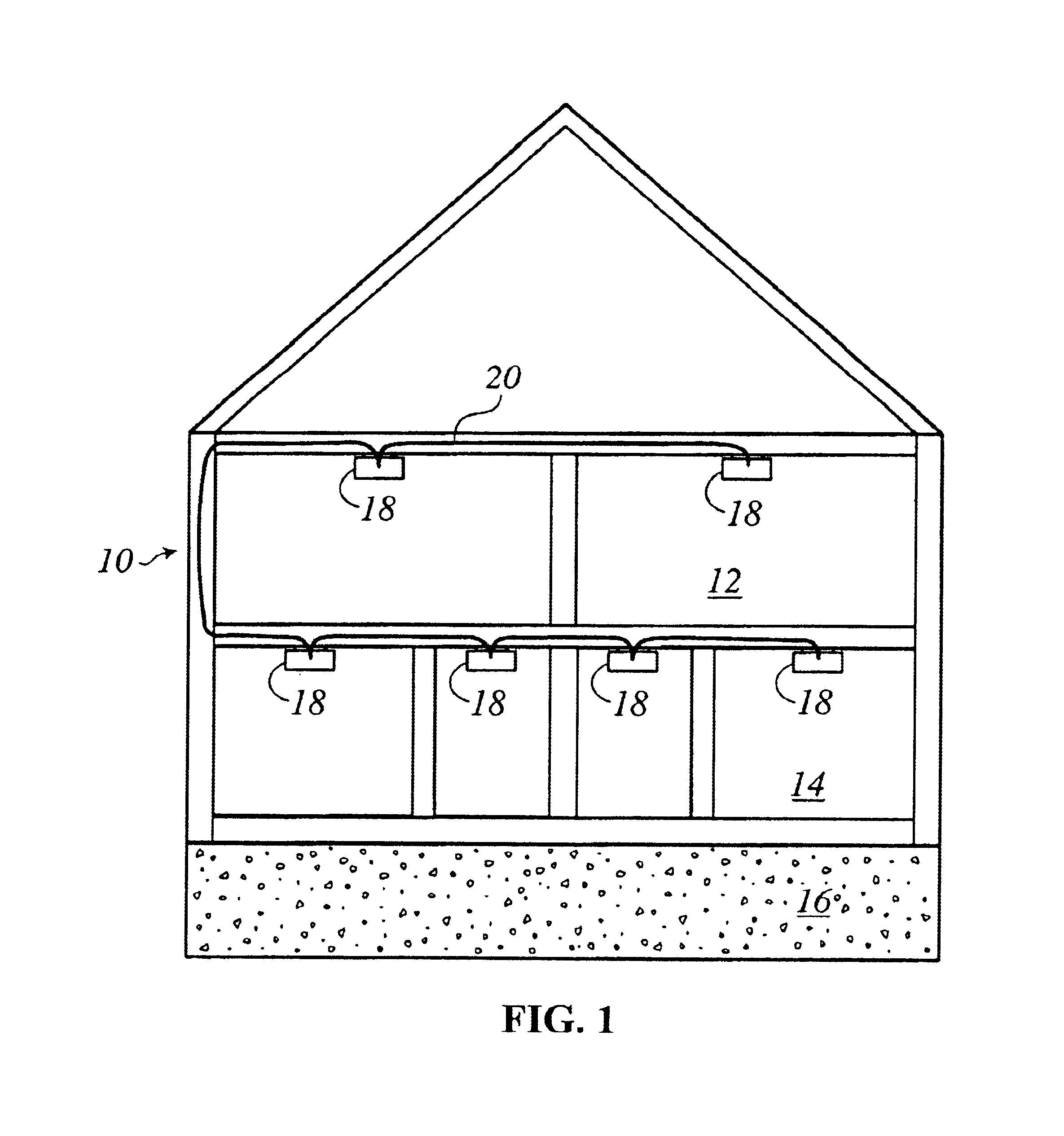
[0028]FIG. 1 illustrates a facility 10 having multiple levels 12, 14 and 16 with rooms on each level. As illustrated, an adverse condition detector 18 is located in each of the rooms of the facility 10 and the detectors 18 are interconnected by a pair of common conductors 20. The plurality of adverse condition detectors 18 can communicate with each other through the common conductors 20.

[0029]In FIG. 1, each of the adverse condition detectors 18 is configured to detect a dangerous condition that may exist in the room in which it is positioned. Generally speaking, the adverse condition detector 18 may include any type of device for detecting an adverse condition for the given environment. For example, the detector 18 could be a smoke detector (e.g., ionization, photo-electric) for detecting smoke indicating the presence of a fire. Other detectors could include but are not limited to carbon monoxide detectors, aerosol detectors, gas detectors including combustible, toxic and pollution...


PUM


Abstract

An adverse condition detector that allows the user to visually determine the type of adverse condition being detected. The adverse condition detector includes a sensor and a control unit coupled to the sensor. When the sensor detects an adverse condition above a selected level, the control unit generates an audible alarm signal and a visual alarm signal. The visual alarm signal simulates the type of adverse condition being detected. In one embodiment of the invention, the visual alarm signal includes a plurality of visual indicators operated in a random fashion to simulate the appearance of a flame.

Description

BACKGROUND OF THE INVENTION[0001]The present invention generally relates to an adverse condition detector that includes a sensor for detecting an adverse condition in a building. More specifically, the present invention is directed to a method and apparatus for providing an enhanced visual alarm signal such that the user can more quickly and easily determine what type of adverse condition is being sensed by the adverse condition detector.[0002]Alarm systems that detect dangerous conditions in a home or business, such as the presence of smoke, carbon dioxide or other hazardous elements, are extensively used to prevent death or injury. In recent years, it has been the practice to develop adverse condition detectors that detect more than one type of adverse condition within a single unit. For example, detectors are currently available that include multiple sensors, such as a CO sensor and a smoke sensor, such that if either of these adverse conditions is detected, the single adverse co...

Claims


Application Information

Patent Timeline
Patent Type & Authority Patents(United States)
IPC IPC(8): G08B5/38G08B5/22
CPCG08B5/38
Inventor TANGUAY, WILLIAM P.
Owner MAPLE CHASE
Why Eureka
Try Eureka