
Utility control and autonomous disconnection of distributed generation from a power distribution system

Inactive Publication Date: 2005-07-05
WELLSPRING HERITAGE
View PDF9 Cites 44 Cited by
  • Summary
  • Abstract
  • Description
  • Claims
  • Application Information

AI Technical Summary

Benefits of technology

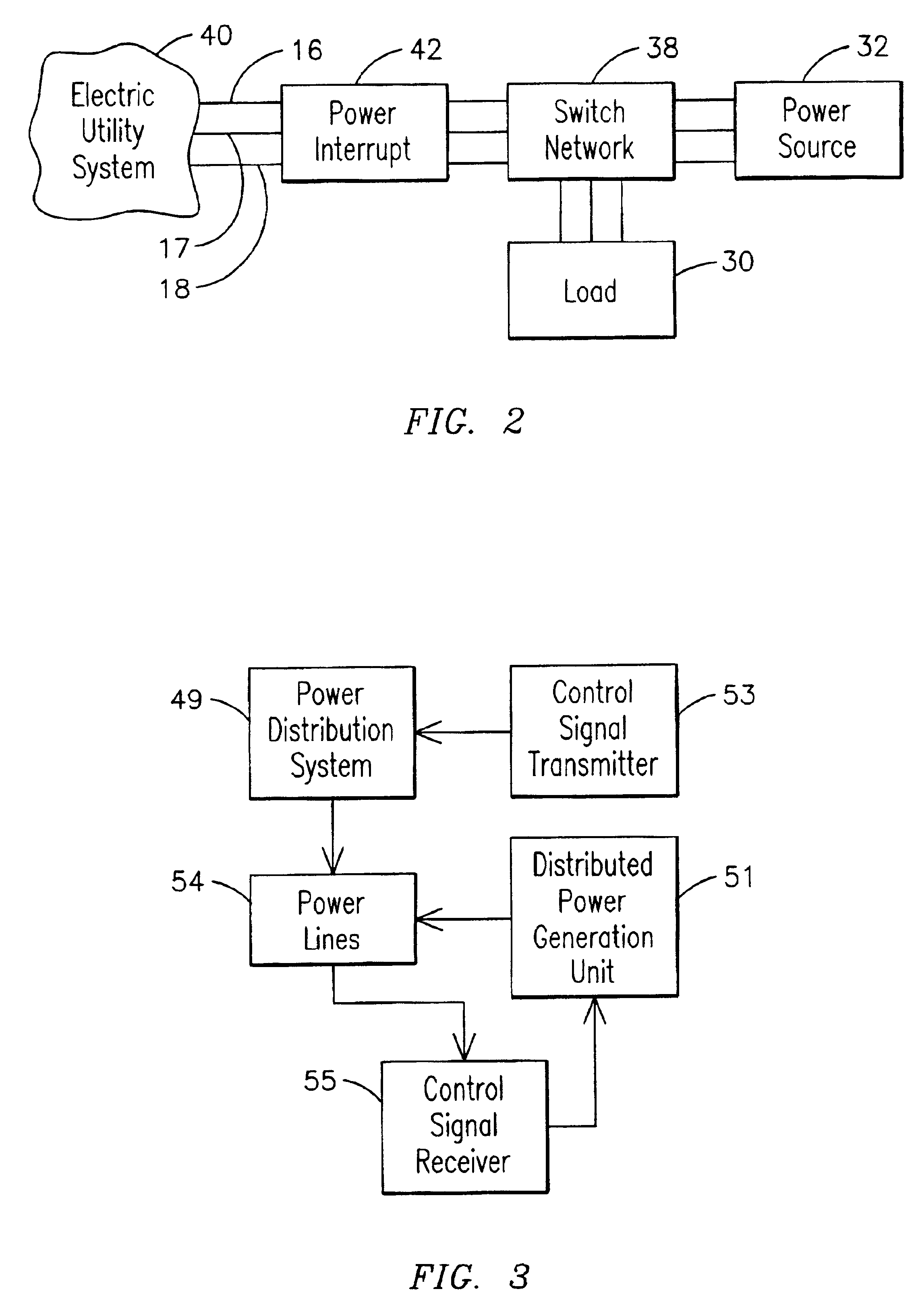
[0011]The present invention is directed to a system and method for disconnecting power distributed generation units from a faulted power line, such as upon occurrence of a broken conductor, or whenever the primary electric utility power supplier determines that it is necessary to disconnect distributed generation units from the power grid. The invention is applicable to a system which comprises a power distribution system to which both a primary electric utility company and one or more distributed power generation units are supplying alternating current (AC) power. In one form, the system includes at least one control signal transmitter for transmitting a control signal over each of a plurality of individual power lines of the power distribution system. The transmitters may be connected such that there is a specific transmitter for each phase of a 3-phase power system with each transmitter transmitting a unique signal associated with that particular phase or the system may be set up such that the same signal is transmitted on each phase of the power distribution system. At each distributed generation unit there is provided a control signal receiver for receiving the signals generated by the transmitters. The control signal receivers are connected to a control system that is coupled to a set of circuit breakers or switches that can be used to disconnect the distributed power generation unit from the electric power utility system.
[0012]In one form, each of the control signal receivers is coupled to the control system such that these circuit brea

Problems solved by technology

For this reason, electric power grids are growing increasingly complex and interconnected, with a greater number of power buyers and sellers making a burgeoning number of transactions.
Safety of the general public is greatly compromised when an overhead distribution or transmission line conductor falls to the ground.
However, the primary electric utility company may not have control over other distributed generation units which may be coupled to the downed conductor or to the power distribution lines downstream of the downed or broken conductor.
Consequently, the grid in the area of the downed conductor may remain energized even though the primary power to the area has been interrupted.
Since there is no physical difference between the different phase conductors, no simple visual identification is possible.
Once a power outage occurs in an electric power grid, restoration may be a difficult and lengthy process, possibly requiring many hours.
If a significant portion of the generation of the interconnected system comes from distributed generation units, conventional control and communication channels may not be adequate for the required control.
When the control system of the distributed generation unit must rely on detection of certain anomalous conditions of the utility distribution line before recognizing the necessity of immediate isolation from the circuit, it is often too late, and the conditions too severe, to maintain the normal output of the distributed generation unit or generator.
If the owner of the distributed generation unit depends on this generator for emergency power supply when the normal utility supply is disrupted, this sequence is operationally undesirable, and may cause economic hardship, such as loss of product or services.

Method used


Image

  • Utility control and autonomous disconnection of distributed generation from a power distribution system
  • Utility control and autonomous disconnection of distributed generation from a power distribution system
  • Utility control and autonomous disconnection of distributed generation from a power distribution system

Examples


Embodiment Construction

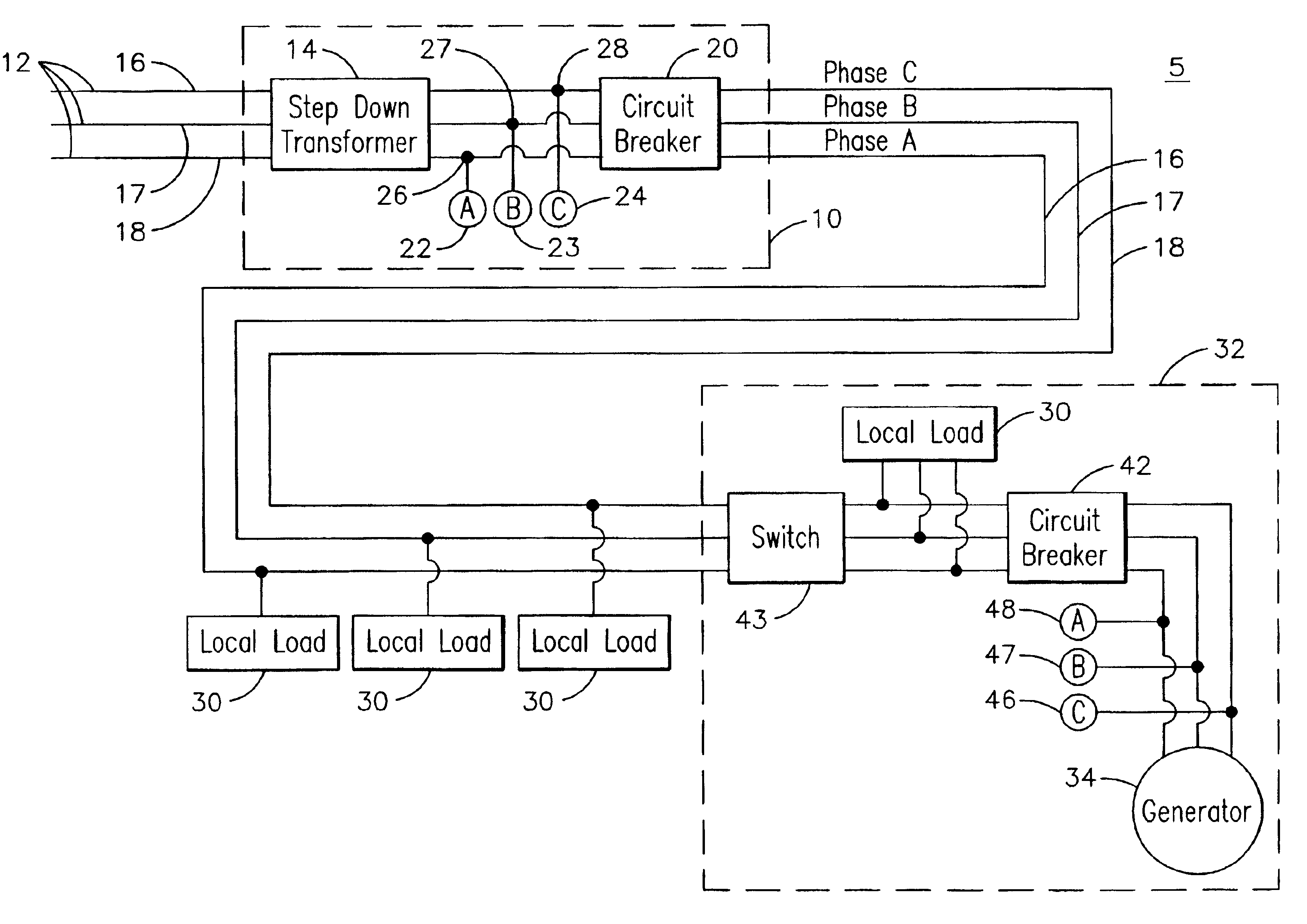
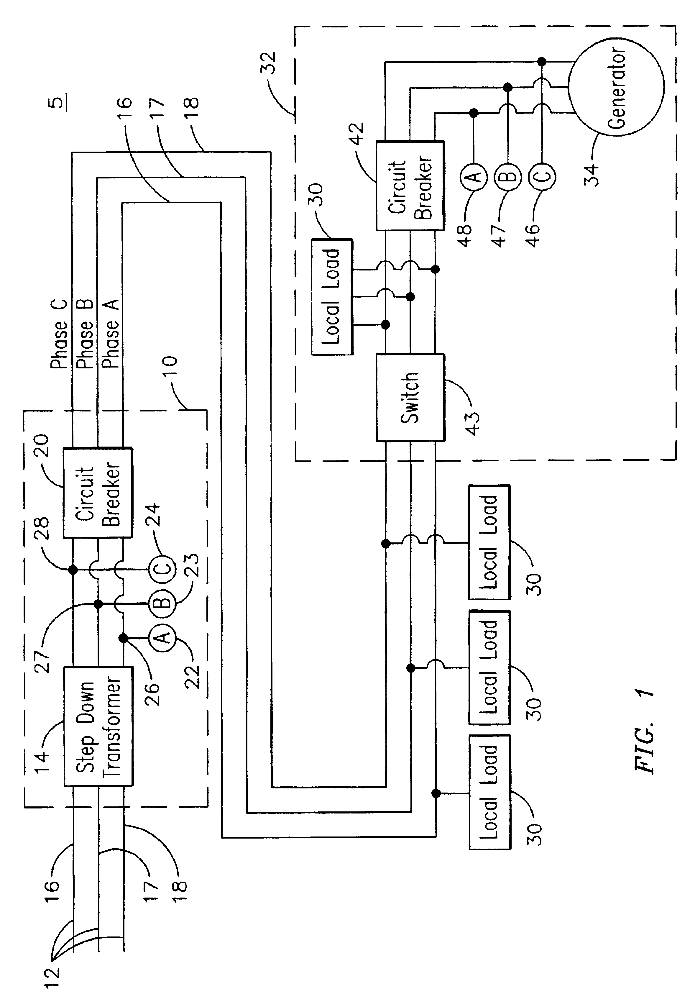
[0017]FIG. 1 is an exemplary block diagram of one form of the present invention. As is well known, a primary electric utility power company supplies electric power to elements of an electric power grid through a plurality of substations such as an electric utility substation 10. The electrical power is supplied through electrical utility transmission lines 12 from a source, such as a coal fired or nuclear power plant, to the electric utility substation 10. In the electric utility substation 10, the electrical power is supplied to transformers 14, where the voltage is stepped down, typically from the tens or hundreds of thousands of volts range, to a lower voltage, typically less than 30,000 volts. The stepped down electrical power is then fed through one or more circuit breakers 20 to the local distribution circuit represented by conductor lines 16, 17 and 18. As is well known, the electric power is distributed as three-phase AC power.

[0018]The present invention incorporates control...


PUM


Abstract

In a utility power distribution system having at least one primary electric power source and at least one secondary electric power source, each of said primary and secondary sources being connected to the distribution system through respective controllable circuit breakers, the improvement comprising communication signal generating apparatus arranged for introducing a communication signal into the power distribution system from the connection of the primary power source, communication signal receiving apparatus arranged for receiving the communication signal via the power distribution system at the secondary power source, and apparatus responsive to the interruption of receipt of the communication signal at the receiving apparatus for operating the circuit breakers at the secondary power source for disconnecting the secondary power source from the power distribution system.

Description

SPECIFIC DATA RELATED TO THE INVENTION[0001]This application claims benefit of U.S. provisional application Ser. No. 60 / 348,912 filed Jan. 15, 2002.BACKGROUND OF THE INVENTION[0002]This invention relates to an electric power generation system and, more particularly, to a method and system for disconnecting a distributed power generation unit from a power distribution system.[0003]An electric power system of a country, such as the United States, typically consists of large, regional power systems interconnected to form an electric power grid or circuit. Primary electric power in any region is provided by a government-regulated electric utility company, which may be investor owned, membership owned, or government owned. A regional grid is dynamic and may comprise a plurality of distributed generation units, or producers of electrical power that are directly connected to a power distribution system or grid that is privately owned and maintained by entities other than the electric utili...

Claims


Application Information

Patent Timeline
IPC IPC(8): H02H7/26H02H11/00
CPCH02H7/262H02H11/008
Inventor REEDY, IRVING
Owner WELLSPRING HERITAGE
Learn More