Identification method for cross directional position correspondence and manufacturing equipment using this method for sheet form products

a technology of cross-directional position and manufacturing equipment, which is applied in the direction of instruments, papermaking, textiles and papermaking, etc., can solve the problems of difficult to maintain good profiles, difficult to implement the test during machine operation in view of quality control, and impose a large load on tuning operators, so as to give stability to optimization and stability to optimization

Active Publication Date: 2005-07-05
YOKOGAWA ELECTRIC CORP
View PDF12 Cites 5 Cited by
  • Summary
  • Abstract
  • Description
  • Claims
  • Application Information

AI Technical Summary

Benefits of technology

[0026]In claim 13 of the present invention, the position correspondence optimization portion in any of claims 9 to 12 described above determines the above position correspondence modification amount using the steepest descent method. This enables the solution to be obtained simply and rapidly.
[0027]In claim 14 of the present invention, the position correspondence optimization portion in claim 13 described above interpolates the modification amount determined by the above steepest descent method with the interpolation calculation using a neural network. Dispersion of the position correspondence modification amount in the cross direction caused by the dispersion of the amount of control action can be smoothly interpolated.
[0028]In accordance with claim 15 of the present invention, in claim 13 described above, the specific limit values are set and the above modification amount is modified so that the above modification amount does not take a value outside the region within the limit values. This can give stability to the optimization.
[0029]In accordance with claim 16 of the present invention, in claim 14 described above, the specific limit values are set and the above modification amount is modified so that it does not take a value outside the region within the limit values. This can give stability to the optimization.

Problems solved by technology

During implementation of the automatic step response test, it is difficult to maintain good profiles because the number of manipulating bolts of the actuators and manipulated variables of the actuators are limited and thus it is difficult to implement the test during machine operation in view of quality control.
However, determination of position correspondence between the actuators and the measuring points by such a method has the following problems:
This results in the problem of a very great load being imposed on the tuning operators.
However, there is also the problem that the position correspondence must be identified by implementing an automatic step response test for each recipe and considerable man hours become necessary for tuning work.
Further, if the machine operating conditions such as basis weight and machine speed or other production conditions change, position correspondence changes even if the raw material recipe remains the same, and the above determination method cannot cope with such cases.
Thus there is also another problem with the above method in that controllability deteriorates resulting in the production of defective products.

Method used


Image

  • Identification method for cross directional position correspondence and manufacturing equipment using this method for sheet form products
  • Identification method for cross directional position correspondence and manufacturing equipment using this method for sheet form products
  • Identification method for cross directional position correspondence and manufacturing equipment using this method for sheet form products

Examples


Embodiment Construction

[0041]The present invention will be described below in detail based on the drawings.

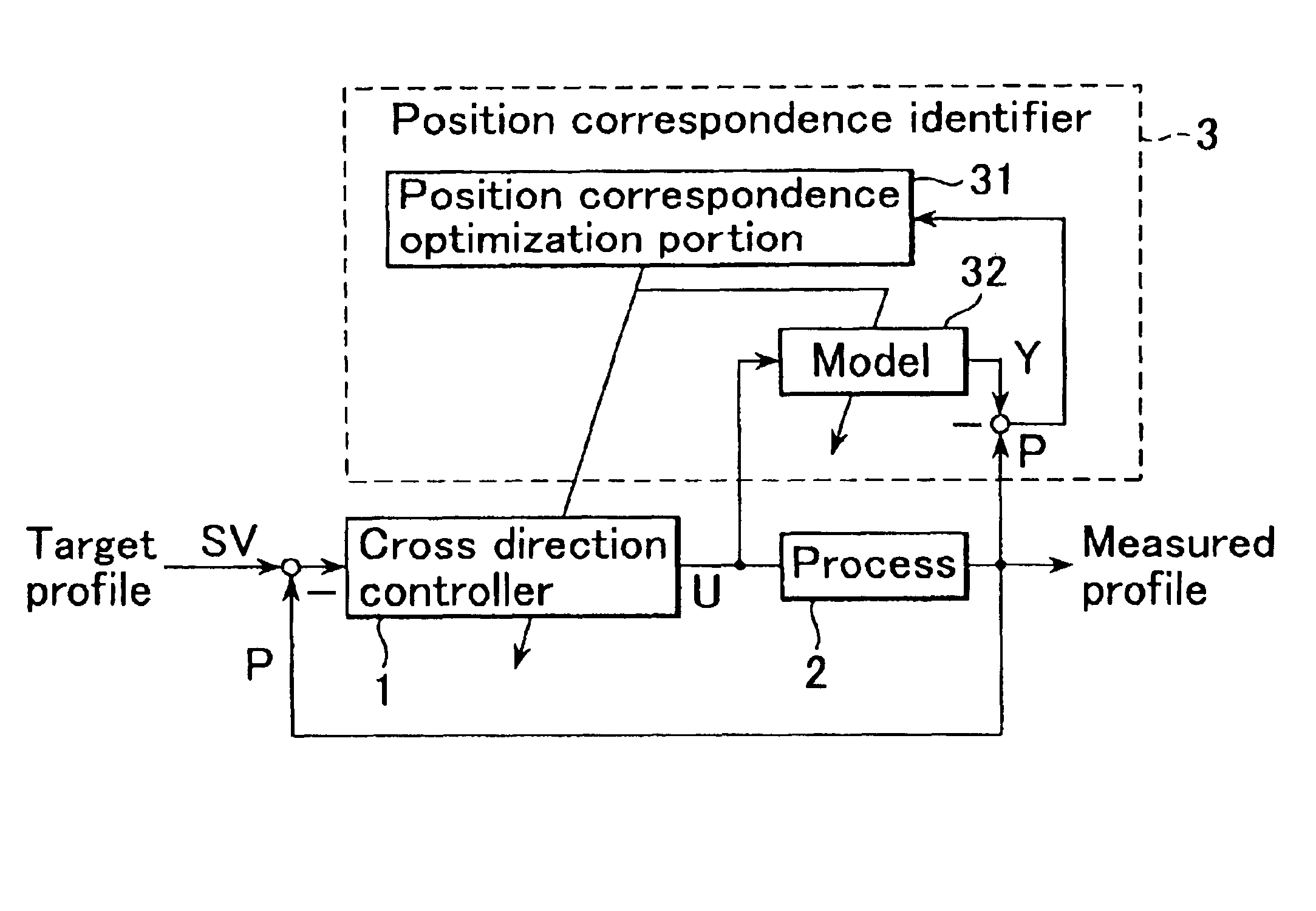
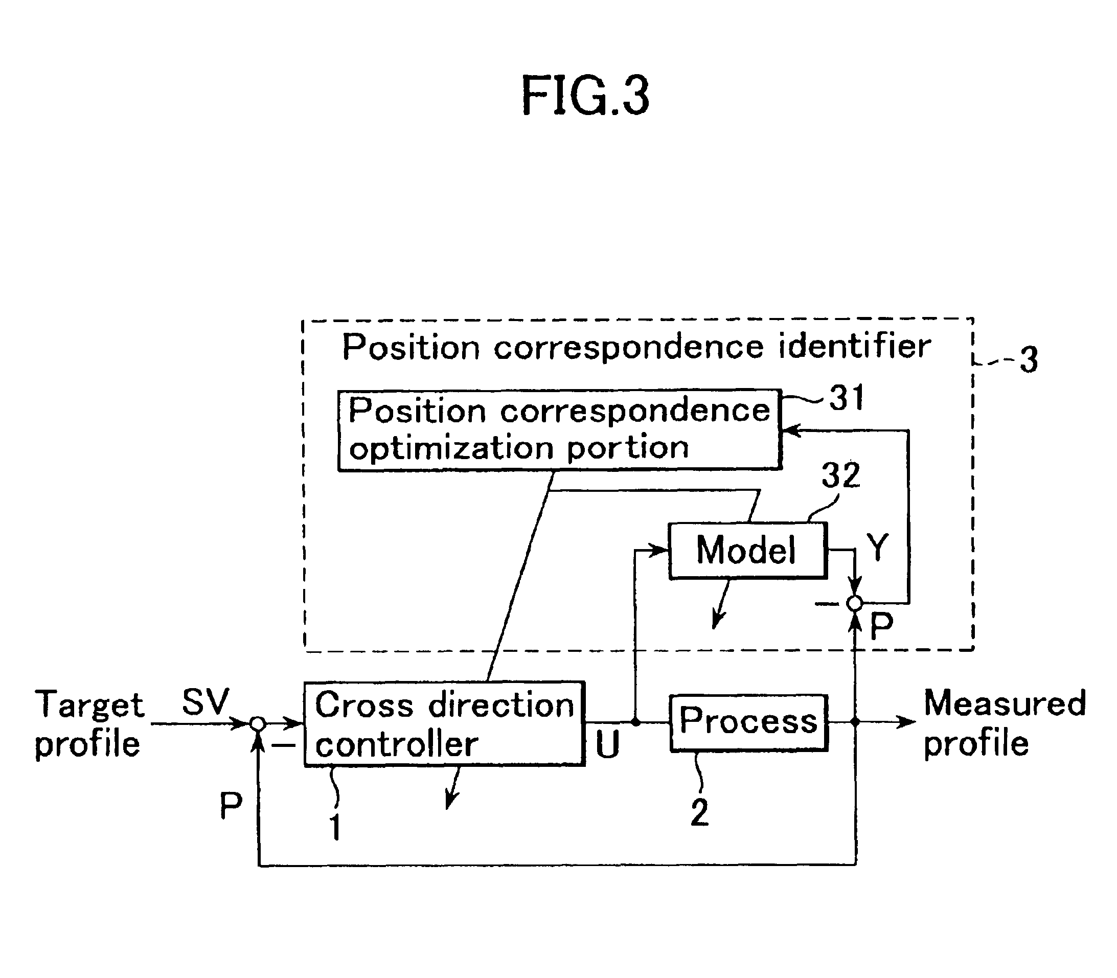
[0042]FIG. 3 is a configuration drawing indicating an embodiment of the present invention for manufacturing equipment for sheet form products. In FIG. 3, numeral 1 denotes a cross direction controller which receives a deviation between target profile SV and measured profile P as an input. Cross direction controller 1 calculates the optimum manipulated amount U from this deviation and outputs the amount U. Numeral 2 shows a process that produces sheet form products and receives a manipulated amount U as the input. Process 2 produces sheet form products as well as outputs a sheet's cross direction measured profile P.

[0043]Numeral 3 denotes a position correspondence identifier which is composed of position correspondence optimization portion 31 and model 32. Model 32 simulates process 2, receives manipulated amount U as the input and outputs profile response Y. The deviation between profile response Y a...


PUM


Abstract

The present invention solves the quality control problems that exist in manufacturing equipment for sheet form products, that is, although the position correspondence between actuators and measuring points has been measured and switched for every raw material recipe, it takes a lot of time and effort and if the position correspondence shifts during machine operation, the position correspondence must be measured again by measuring step responses.
According to the present invention, the position correspondence, interference width, and process gain of a process model are modified so that the deviation between the process model and the measured profile is minimized by inputting the manipulated variable of the actuators to the process model. This position correspondence is also set to a cross direction controller that outputs the manipulated variable. Since this enables the position correspondence to be modified in succession to the optimum value during machine operation, it prevents controllability from deteriorating even if the position correspondence shifts, thereby eliminating time and effort for measuring and switching position correspondences for each raw material recipe.

Description

BACKGROUND OF THE INVENTION[0001]1. Field of the Invention[0002]The present invention relates to an identification method for cross directional position correspondence in equipment that manufactures sheet form products, in which the position correspondence between actuators for controlling cross direction profiles of the sheet and measuring points for these profiles can be automatically identified, and to manufacturing equipment using this method for sheet form products.[0003]2. Description of the Prior Art[0004]FIG. 1 shows a configuration of a portion to control cross direction profiles in the equipment for manufacturing sheet form products such as paper. Hereafter description will be made pertaining to paper manufacturing equipment. In FIG. 1, the raw material pulp is made into sheet form by being sent out to wire part 42 from the gap of slice lip 41. The width of the gap of slice lip 41 is adjusted by slice bolts 43. Moisture contained in the pulp which has been made into sheet ...

Claims


Application Information

Patent Timeline
Patent Type & Authority Patents(United States)
IPC IPC(8): G06F7/66G06F7/60D21G9/00
CPCD21G9/0027
Inventor SASAKI, TAKASHI
Owner YOKOGAWA ELECTRIC CORP
Why Eureka
Try Eureka