Device for determining at least one parameter of a medium flowing in a conduit

a technology of at least one parameter and a conduit, which is applied in the direction of volume metering, machines/engines, instruments, etc., can solve the problems of unprotected sensors and unprotected sensors of air flow meters, and achieve the effect of improving the measuring result and better deflection

Inactive Publication Date: 2005-07-12
ROBERT BOSCH GMBH
View PDF23 Cites 28 Cited by
  • Summary
  • Abstract
  • Description
  • Claims
  • Application Information

AI Technical Summary

Benefits of technology

[0010]By contrast, the device according to the present invention has the advantage that, in a simple way, liquid and or solid particles are not able to reach into the measuring channel.
[0011]By this positioning of a separation opening in the bypass channel, optimum protection of a measuring element from liquid or solid particles is achieved.
[0013]It is of advantage if there is a tear-off edge in an input region of the bypass channel, so that no liquid film can get into the measuring channel via a bypass channel inner wall surface, because the liquid film is detached by the tear-off edge.
[0014]So as to improve the measuring result, the measuring channel tapers in the region of the measuring element. If a wedge is present in the downstream region of the input region, in an advantageous manner a better deflection can be achieved of the water particles and solid particles to the separation openings, and it may be avoided that water particles or solid particles collect at a baffle plate in the upstream region.

Problems solved by technology

However, in this device, liquid or solid particles present in the medium first flow past the measuring element, and are able to dirty and damage the latter, so as then partially to flow back through the separation opening into the line.
However, sensors of the air flow meter are situated unprotected in the bypass channel.

Method used


Image

  • Device for determining at least one parameter of a medium flowing in a conduit
  • Device for determining at least one parameter of a medium flowing in a conduit
  • Device for determining at least one parameter of a medium flowing in a conduit

Examples


Embodiment Construction

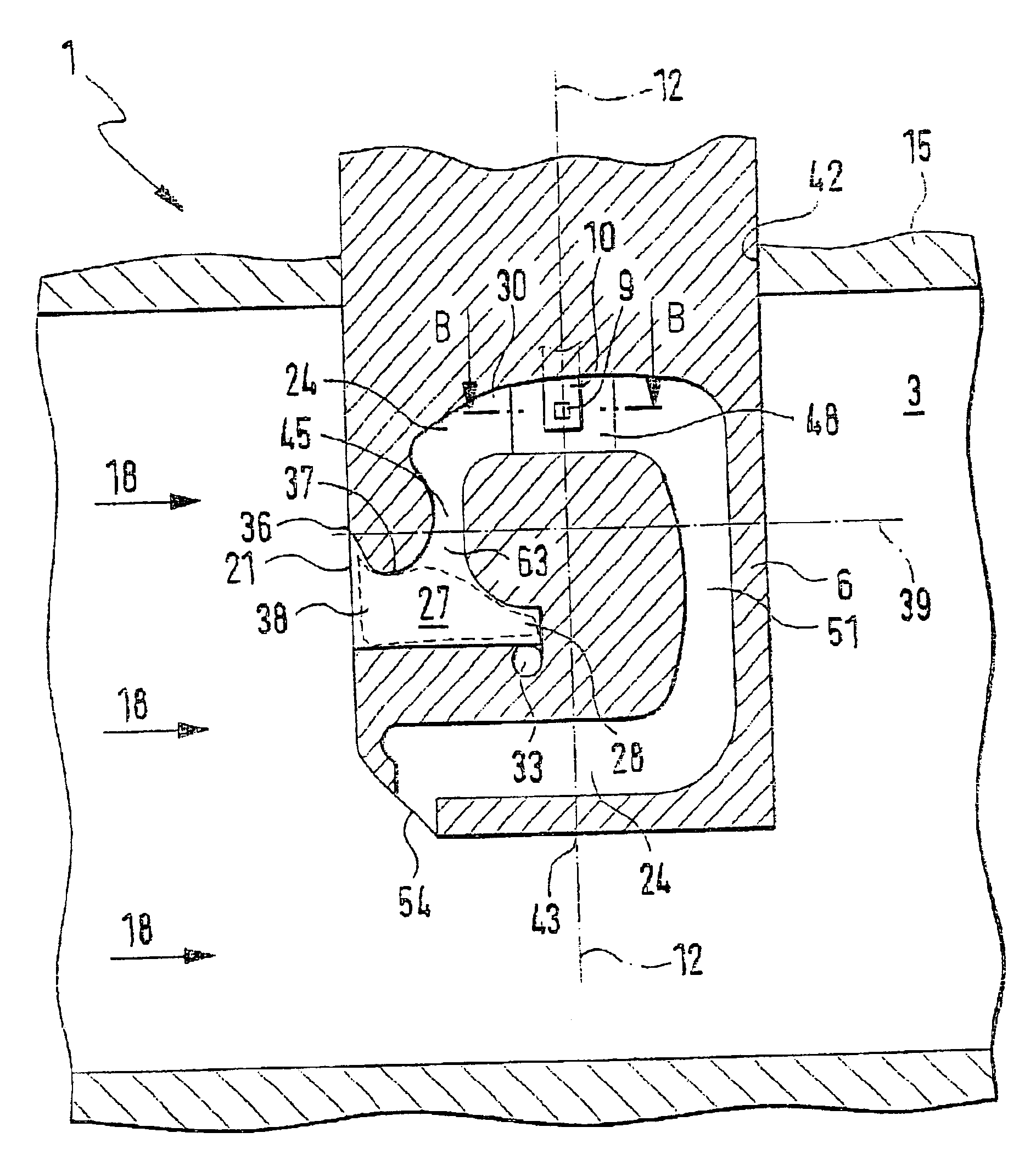
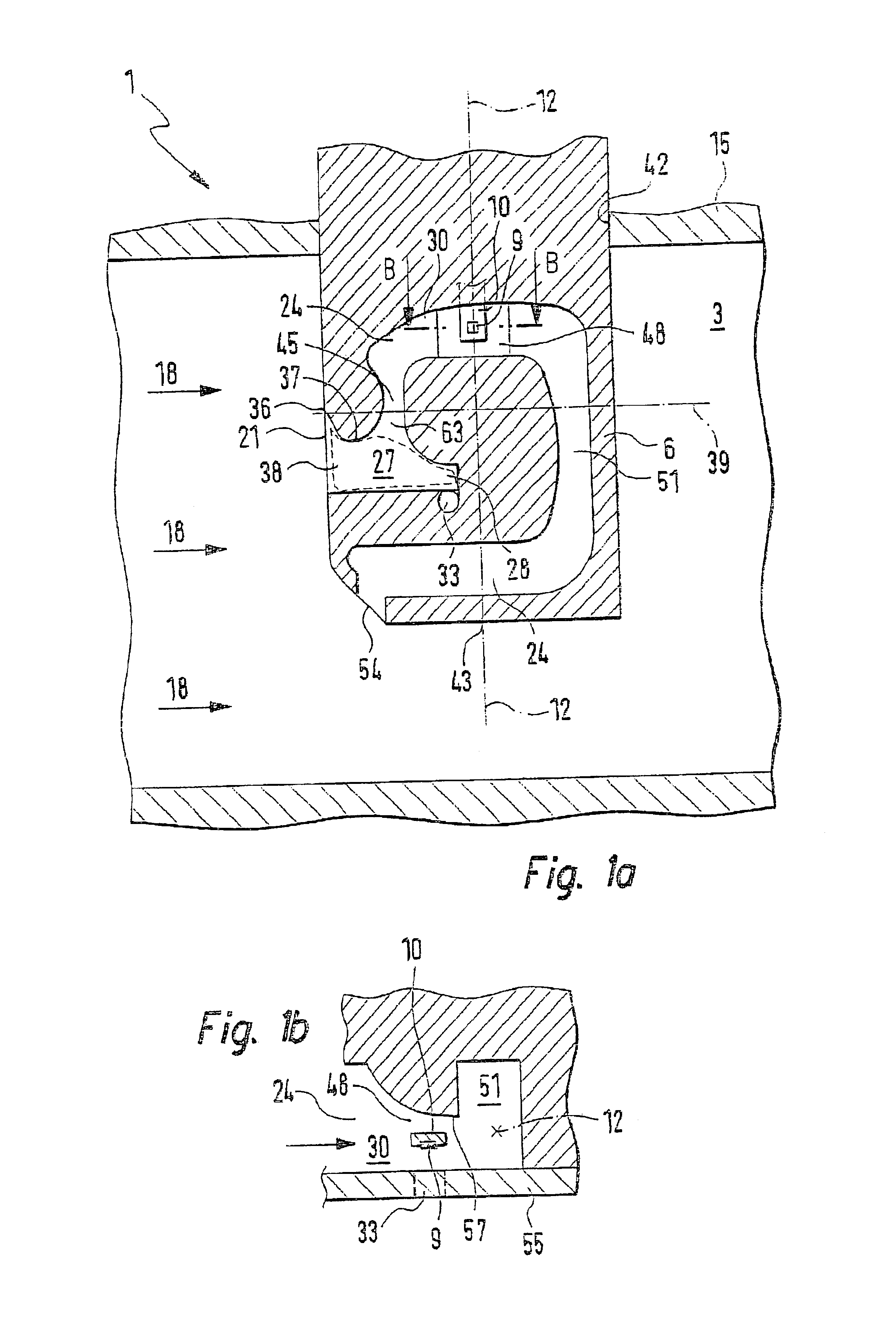
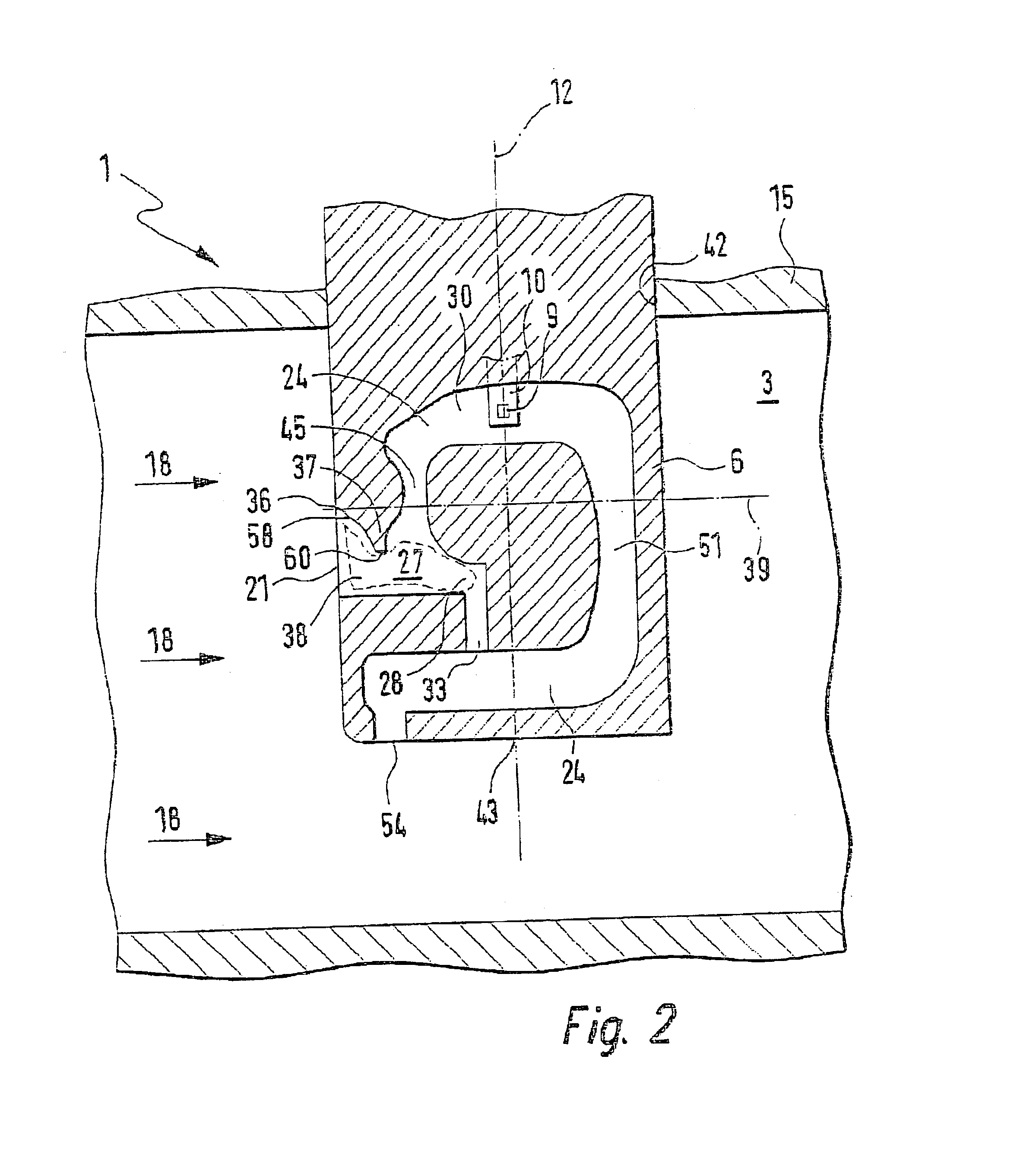
[0021]FIGS. 1a and 1b show how a device 1 according to the present invention is built into a line 3, in which the medium flows. Device 1 for determining at least one parameter of the medium is made up of a measuring housing 6 and a carrying part, not shown in detail, in which, for instance, an evaluation electronic mechanism may be accommodated. Measuring housing 6 having the carrier part is inserted into a wall 15 of line 3, through an insertion opening 42, for instance in a pluggable manner. Wall 15 borders a flow cross section of line 3. In this context, the carrier part is, for example, closest to insertion opening 42, the evaluation electronic mechanism being able to lie within and / or outside the flowing cross section of line 3. For example, in device 1 a measuring element 9 on a measuring element carrier 10 is used, which determines as a parameter, for instance, the volume flow of the flowing medium. Additional parameters which may be measured are, for instance, pressure, temp...


PUM


Abstract

A device for determining a parameter of a medium flowing in a line, according to the related art, does not offer sufficient protection for a measuring element from liquid or solid particles which may dirty or damage the measuring element in an unwanted way. A device has an input region, whence, on the one hand, the flowing medium flows into the measuring channel, and on the other hand, through at least one separation opening, liquid and solid particles flow, and thus flow so as to bypass the measuring channel.

Description

[0001]This application is application is a 371 of PCT / DE 02 / 01363 dated Apr. 12, 2002.FIELD OF THE INVENTION[0002]The present invention relates to a device for determining at least one parameter of a medium flowing in a line.BACKGROUND INFORMATION[0003]A device is known from German Published Patent Application No. 196 23 334 and U.S. Pat. No. 6,148,663 for determining the mass of a medium flowing in a line in which there is a separation opening in a bypass channel. However, in this device, liquid or solid particles present in the medium first flow past the measuring element, and are able to dirty and damage the latter, so as then partially to flow back through the separation opening into the line.[0004]German Published Patent Application No. 198 15 654 shows a device for determining the mass of a medium flowing in a line in which a separation point is present in the bypass channel. The separation point is formed by a separation wall which subdivides the bypass channel into a measuri...

Claims


Application Information

Patent Timeline
Patent Type & Authority Patents(United States)
IPC IPC(8): G01F1/684G01F15/00G01F15/12G01F1/00F02D35/00
CPCG01F1/6842G01F15/12G01F1/00
Inventor RENNINGER, ERHARDLENZING, THOMASFISCHER, MANFREDKONZELMANN, UWESIPPEL, MARKUS
Owner ROBERT BOSCH GMBH
Why Eureka
Try Eureka