
Method of producing an enveloping worm

a production method and worm technology, applied in the direction of gear teeth, hoisting equipment, gearing, etc., can solve the problems of reducing the production cost of spiral bevels and hypoids, limiting the use of enveloping worms, and requiring more machining time, so as to achieve high contact ratio and wide use

Inactive Publication Date: 2005-07-12
FLEYTMAN YAKOV
View PDF17 Cites 6 Cited by
  • Summary
  • Abstract
  • Description
  • Claims
  • Application Information

AI Technical Summary

Problems solved by technology

The more expensive cost of production of enveloping worms limits its use only when it is necessary to transfer mechanical power between crossed or intersected shafts.
New technology lowers production cost of spiral bevel and hypoid gears, but to make enveloping gears and especially enveloping worm, more machining time is still required.

Method used


Image

  • Method of producing an enveloping worm
  • Method of producing an enveloping worm
  • Method of producing an enveloping worm

Examples


Embodiment Construction

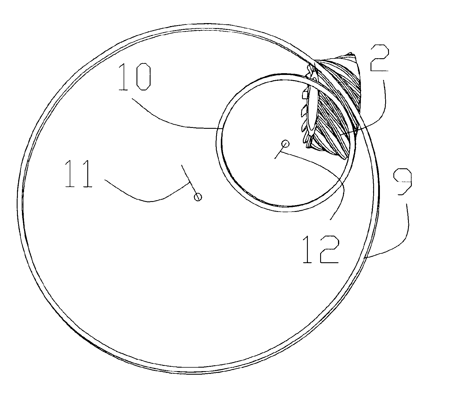
[0024]The following discussion relating to FIGS. 1-21 provides a detailed description of the unique method for manufacturing enveloping worm that can be utilized with the present invention.

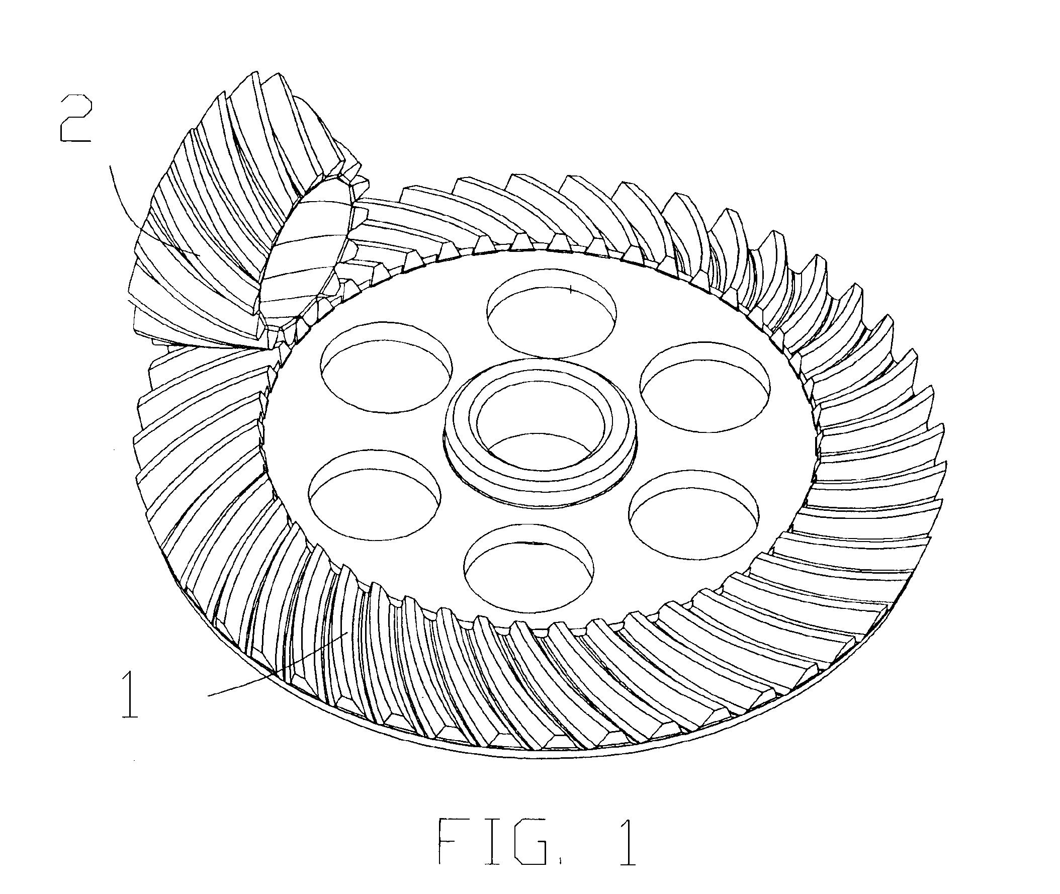
[0025]FIG. 1 is an isometric view of face gear 1 of an enveloping worm face gear transmission in mesh with enveloping worm 2. The enveloping worm face transmission is a new type of right angle gears (U.S. patent application Ser. No. 10 / 435,143). Said enveloping worm 2 having at least one thread that is engaged by at least one tooth of said worm gear 1 wherein said worm gear 1 is a face gear and said enveloping worm 2 is placed into face arrangement with said worm gear 1. In this enveloping worm face transmission the enveloping worm 2 could have any design, however, it is preferred that the enveloping worm is utilized for standard enveloping or double enveloping worm / worm gear transmission. The difference is that we are using threads with less than one revolution.

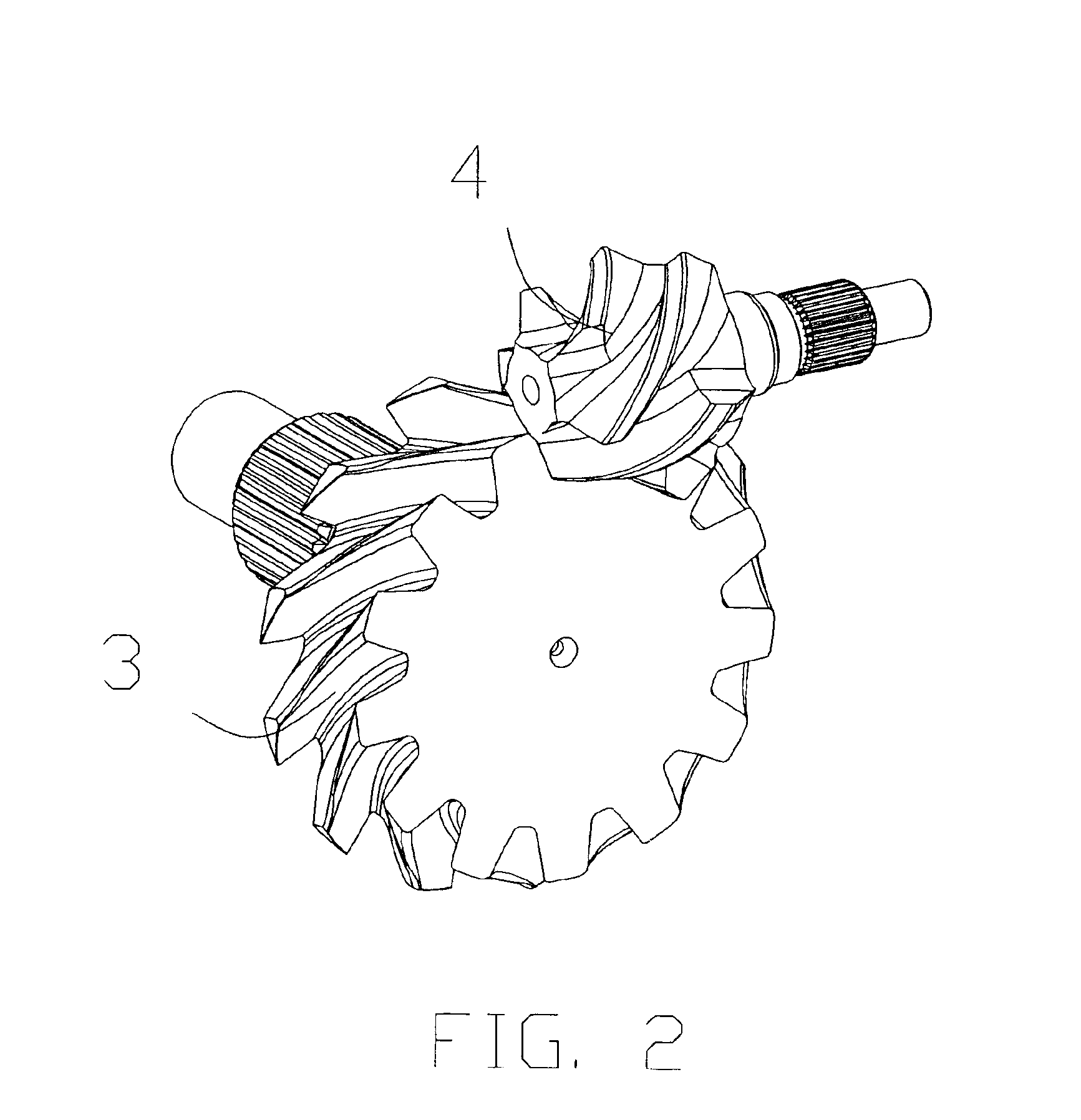
[0026]FIG. 2 is an isometric view w...


PUM

PropertyMeasurementUnit
angleaaaaaaaaaa
radius of convex curvatureaaaaaaaaaa
radiusaaaaaaaaaa

Abstract

Enveloping worm threads with less than one revolution have on one side concave surface and on another side convex surface. This makes generation of concave and convex enveloping worm surfaces simultaneously and makes modification of surfaces by individual machining of each surface. Proposed method uses cutting edges that have rotation radius according with radius of curvature of machining surface. Another variation simultaneously cuts several threads, where enveloping worm blank has rotation around its own axis of rotation and relative motion to helical cutter around tooling axis. This reduces production cost and makes manufacturing easily.

Description

FIELD OF THE INVENTION[0001]The present invention relates to production of an enveloping worm. The enveloping worm is a pinion in two general worm gear units: double enveloping or globoid gears and enveloping worm face gears. They are used to reduce or to increase speed or increase or reduce torque in helicopter or automobile gearboxes, turbine gearboxes, ship's transmission, and industrial applications. Certain applications may be outside of these fields, like power windows, doors or seats, power steering systems, chainless bicycle or motorcycle transmissions, and much more.BACKGROUND OF THE INVENTION[0002]A right angle gear transmission is well known for the transformation of motion and power between shafts where the axes of the pinion and the gear may be crossed or intersected. Recently two new types of enveloping worm gear transmissions from my U.S. Pat. No. 6,148,683 and enveloping face transmission from my patent application Ser. No. 10 / 435,143 made right angle gear transmissi...

Claims


Application Information

Patent Timeline
Patent Type & Authority Patents(United States)
IPC IPC(8): F16H1/04F16H1/16F16H1/12
CPCF16H1/125F16H1/16F16H55/06Y10T74/19953Y10T409/107473Y10T409/101749F16H55/22
Inventor FLEYTMAN, YAKOV
Owner FLEYTMAN YAKOV
Learn More