Cascaded RZ and NRZ laser modulators having RZ/NRZ phase alignment bias control

a laser modulator and phase alignment technology, applied in the field of optical communication systems, can solve the problems of complex hardware for implementing an rz external transmitter, such as long haul, high bit rate fiber communication, etc., and achieve the effect of reducing costs

Inactive Publication Date: 2005-07-12
LUMENTUM OPERATIONS LLC
View PDF8 Cites 14 Cited by
  • Summary
  • Abstract
  • Description
  • Claims
  • Application Information

AI Technical Summary

Benefits of technology

[0009]If the fundamental dither signal is present, the synchronous demodulator produces an error signal that is added to or subtracted from a bias output voltage via an integrator. This bias voltage is used to control an electrical phase delay in the RZ or NRZ signal path. When the RF clock and RF data are aligned in phase, detected RF power is maximized and the detected fundamental dither signal is minimized, so that there will be no error signal present at the output of the synchronous demodulator.
[0010]The second technique is implemented using an RZ quadrature phase dither. A low frequency modulation (dither) signal with low mo

Problems solved by technology

Although an NRZ optical transmitter typically employs only a single electro-optic modulator, the hardware for implementing an RZ external transmitter (such as for l

Method used


Image

  • Cascaded RZ and NRZ laser modulators having RZ/NRZ phase alignment bias control
  • Cascaded RZ and NRZ laser modulators having RZ/NRZ phase alignment bias control
  • Cascaded RZ and NRZ laser modulators having RZ/NRZ phase alignment bias control

Examples


first embodiment

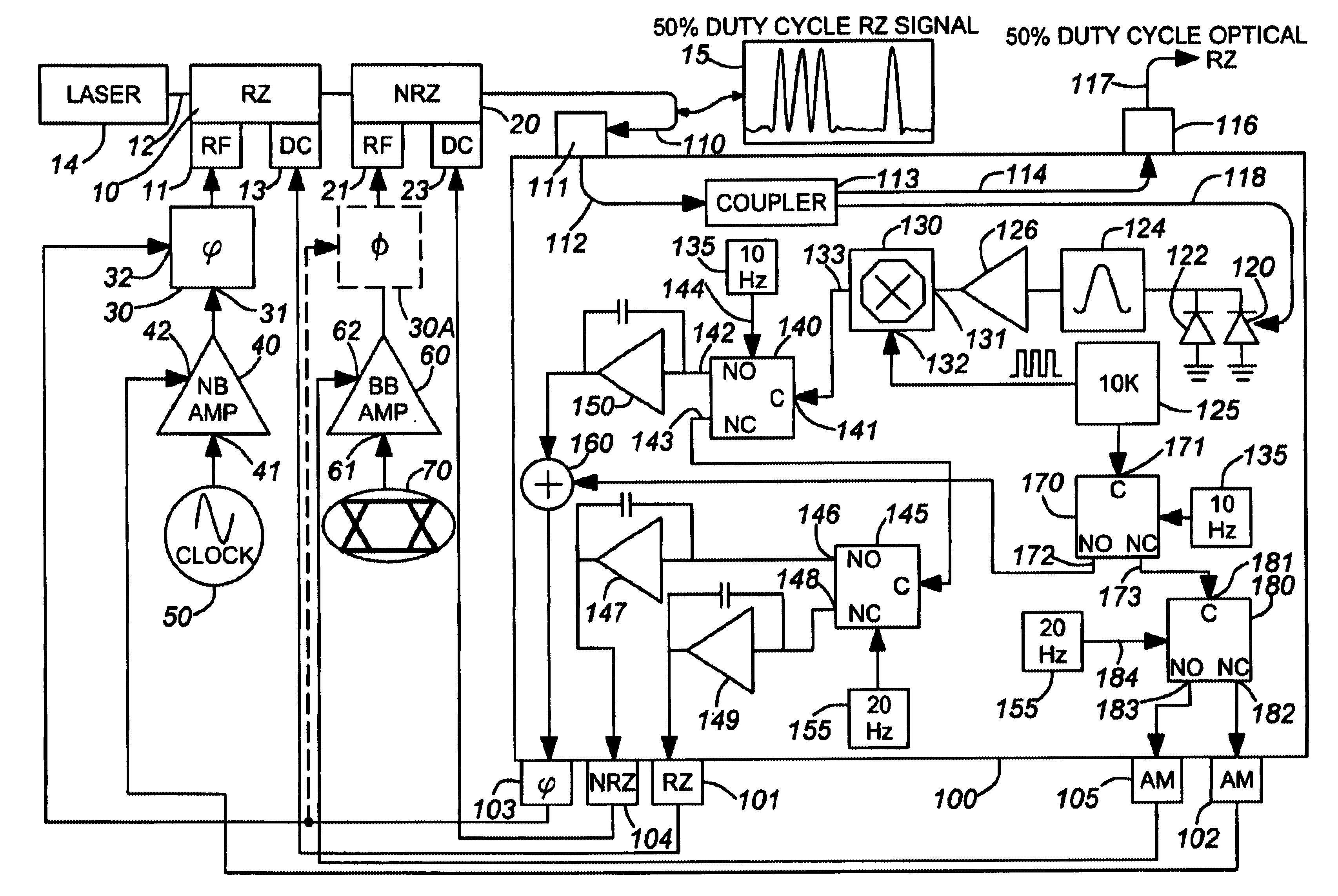
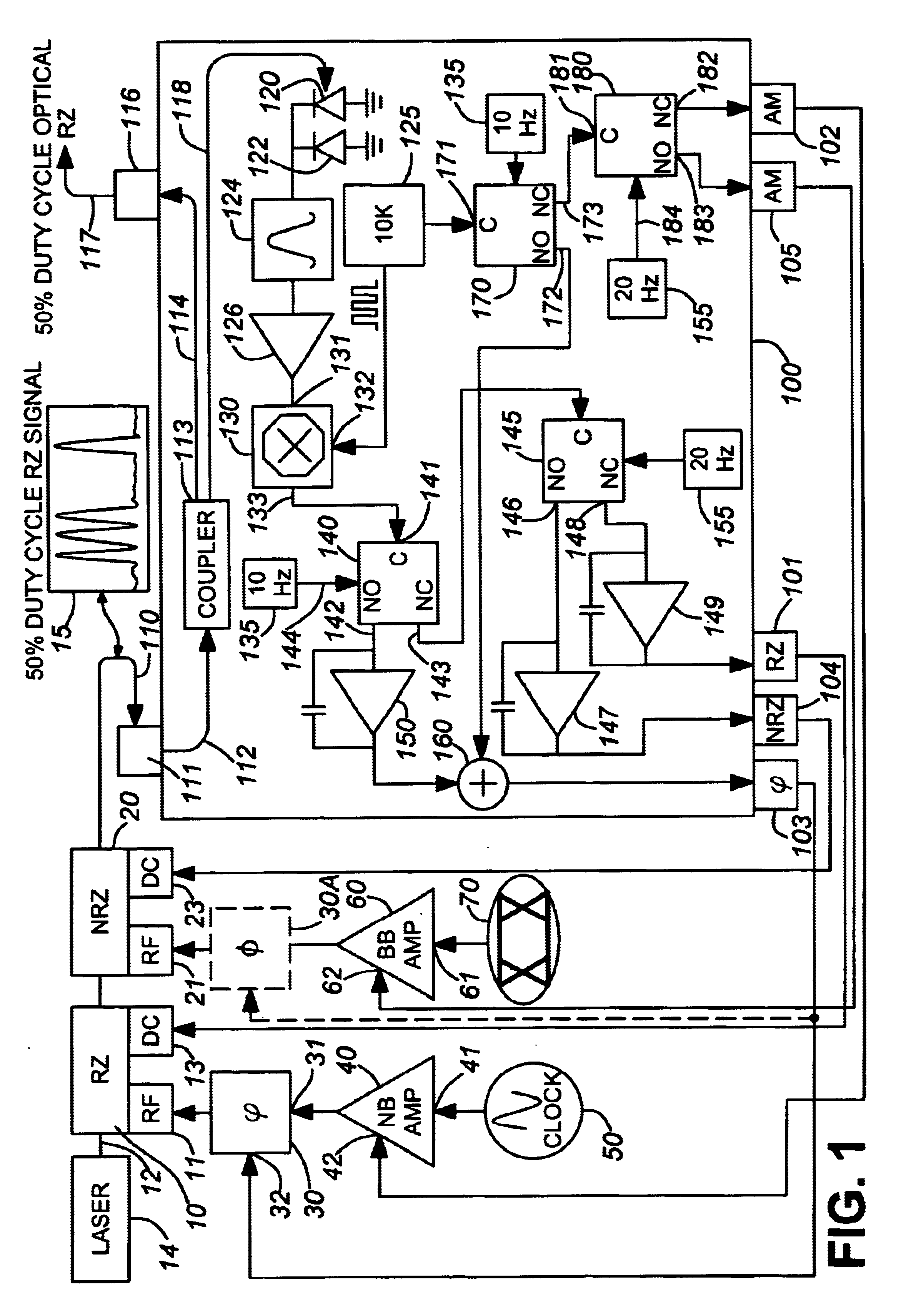
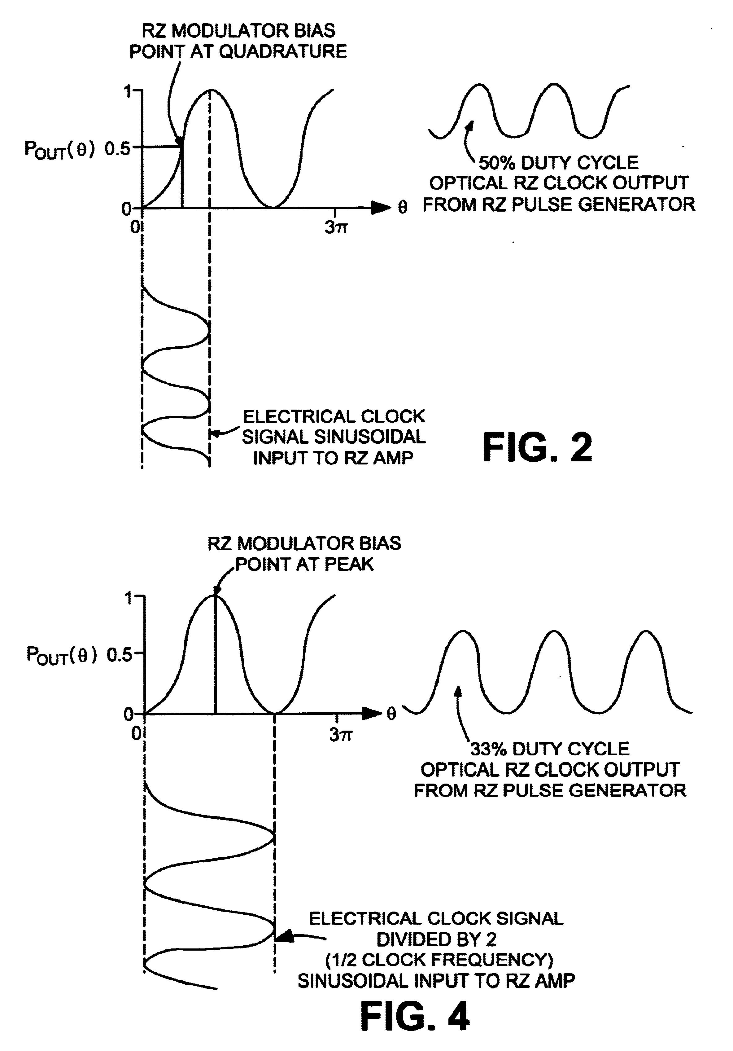
[0017]the cascaded RZ / NRZ digital optical transmitter of the present invention, which employs RZ quadrature bias control and phase alignment of the RZ and NRZ RF signals applied to respective RZ and NRZ modulators is diagrammatically shown in FIG. 1. In this embodiment, the RZ modulator is biased at its transfer function half power point, resulting in an RZ duty cycle of 50%. This larger duty cycle may be preferred in applications where wider RZ pulses are desired.

[0018]Regardless of the biasing control mechanism used, the modulator architecture of each embodiment of the invention comprises a pair of external modulators 10 and 20, which are optically cascaded in the output beam path 12 of a continuous wave laser 14, so as to produce the desired RZ-modulated digital data stream. As a non-limiting example, each of modulators 10 and 20 may comprise an X-cut lithium niobate (LN) Mach Zehnder (MZ) modulator. The relatively upstream modulator 10 serves to modulate the CW laser with a sinu...

third embodiment

[0040]FIG. 5 diagrammatically illustrates the cascaded RZ / NRZ digital optical transmitter of the present invention which employs a modified implementation of the RZ quadrature bias embodiment of FIG. 1, to control the differential phase between the RZ and NRZ RF signals applied to respective RZ and NRZ modulators. As in the embodiment of FIG. 1, the RZ modulator is biased at the mid point of its transfer function, as shown in FIG. 4, so as to realize an RZ duty cycle of 50%. Again, those components of the architecture of the embodiment of FIG. 5 that are the same as in the embodiment of FIG. 1 will not be redescribed here.

[0041]The architecture of FIG. 5 differs from FIG. 1 by simultaneously applying two dither signals to the RZ and NRZ modulators, each having the same modulation index (which may be achieved through manual calibration of the modulator set-up, or automatically (under the control of a transmitter system processor)). Also, the resultant phases of the two optical dither...


PUM


Abstract

An optical transmitter architecture has a return-to-zero (RZ) laser modulator coupled in cascade with a non-return-to-zero (NRZ) laser modulator. Modulator bias and electronic phase delay bias are controlled using dither-based feedback, so as to align the phase of the RZ clock signal with that of the NRZ data. A first method uses an RZ quadrature AM dither or an RZ “hillclimber” bias dither, to apply a relatively low frequency dither signal to a variable RF delay for the RZ clock signal applied to the RZ modulator or NRZ data signal applied to the NRZ modulator. A second method is an RZ quadrature AM dither or “hillclimber” bias dither scheme that applies equal amplitude and opposite phase dither signals to perform complementary modulation of both the RZ and NRZ MZ modulators simultaneously.

Description

CROSS-REFERENCE TO RELATED APPLICATION[0001]The present application is a continuation-in-part of U.S. application Ser. No. 09 / 990,872, filed Nov. 16, 2001 now abandoned, by G. McBrien et al, entitled: “Cascaded Rz and Nrz Laser Modulators Having RZ / NRZ Phase Alignment Bias Control,” and also claims the benefit of co-pending U.S. application Ser. No. 60 / 252,480, filed Nov. 22, 2000, by G. McBrien, et al, entitled: “RZ / NRZ Phase Alignment Bias Control,” each application being assigned to the assignee of the present application and the disclosures of which are incorporated herein.FIELD OF THE INVENTION[0002]The present invention relates in general to optical (e.g., laser-based) communication systems and components therefor, and is particularly directed to a new and improved digital optical transmitter architecture having a return-to-zero (RZ) external modulator coupled in cascade with a non-return-to-zero (NRZ) external modulator, and wherein the DC bias and modulation signal drive lev...

Claims


Application Information

Patent Timeline
IPC IPC(8): H04B10/155H04B10/152
CPCH04B10/505H04B10/50575H04B10/50577H04B10/5162
Inventor MCBRIEN, GREGORY J.FARINA, JOSEPHBORLA, JOHN D.
Owner LUMENTUM OPERATIONS LLC
Why Eureka
Try Eureka