
Communications system with direct access mailbox

a communication system and mailbox technology, applied in the field of telecommunications systems, can solve the problem of providing no means for the called party to control

Active Publication Date: 2010-07-13
BRITISH TELECOMM PLC
View PDF47 Cites 7 Cited by
  • Summary
  • Abstract
  • Description
  • Claims
  • Application Information

AI Technical Summary

Benefits of technology

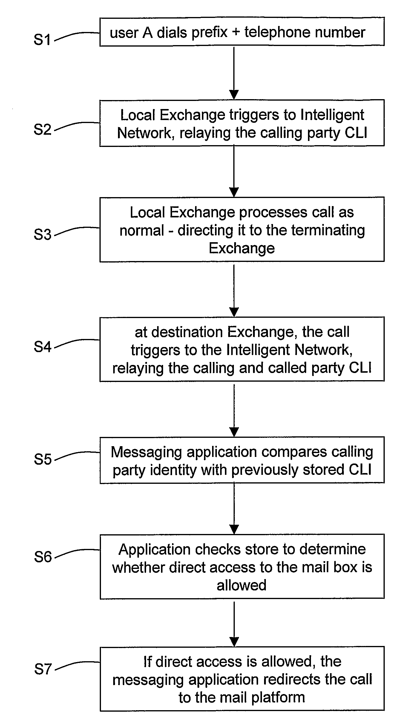
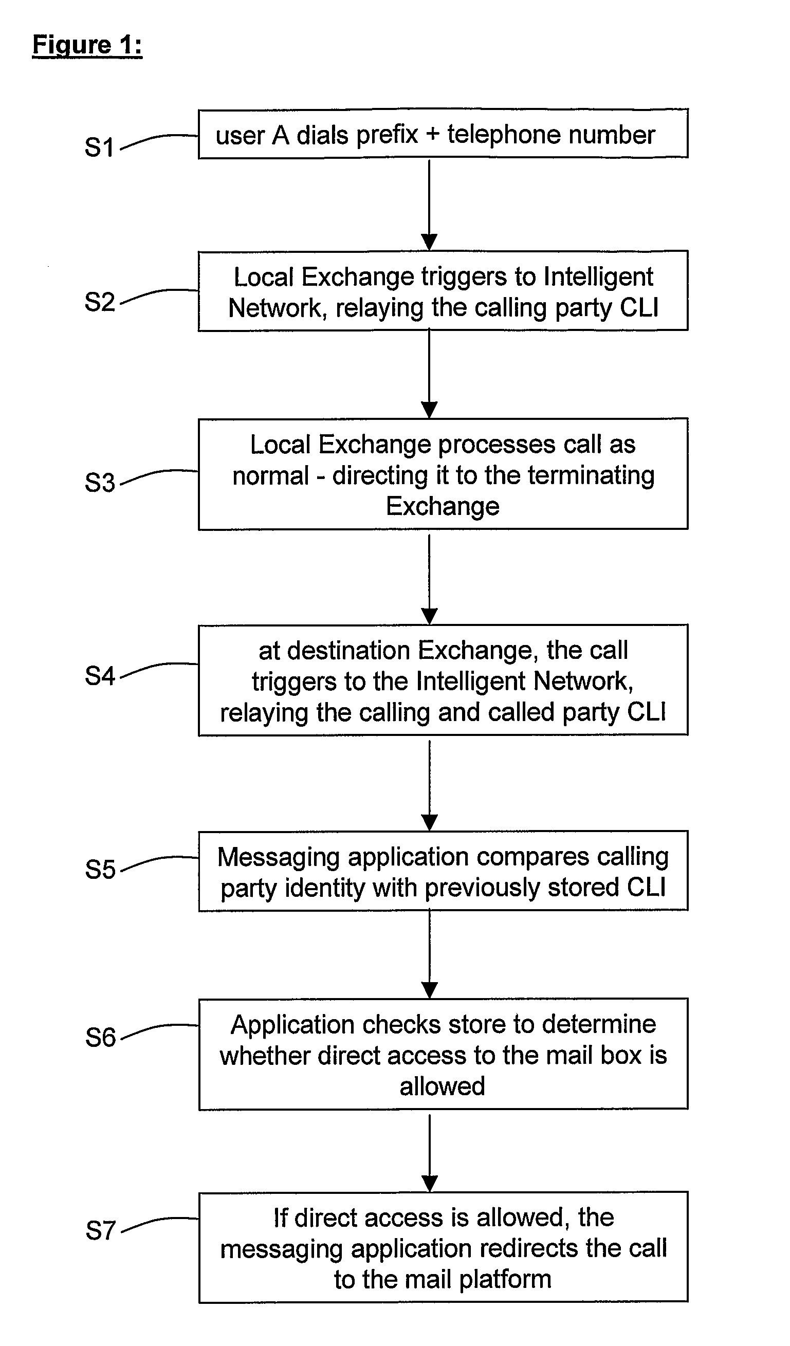
[0019]This aspect conveniently allows the communications system to detect any signals indicating whether the destination user for that particular communication should in the future be allowed to have direct access to the mailbox (e.g. the signal might be a prefix dialled by the second user or a button pressed on a window-based graphical interface to indicate the user's preferences), and the system can act accordingly on the basis of that signal to modify the store (for example, by adding or deleting telephone numbers from the store).

Problems solved by technology

However, this system provides no means for the called party to control who is allowed direct access to their mailbox.

Method used


Image

  • Communications system with direct access mailbox
  • Communications system with direct access mailbox
  • Communications system with direct access mailbox

Examples


second embodiment

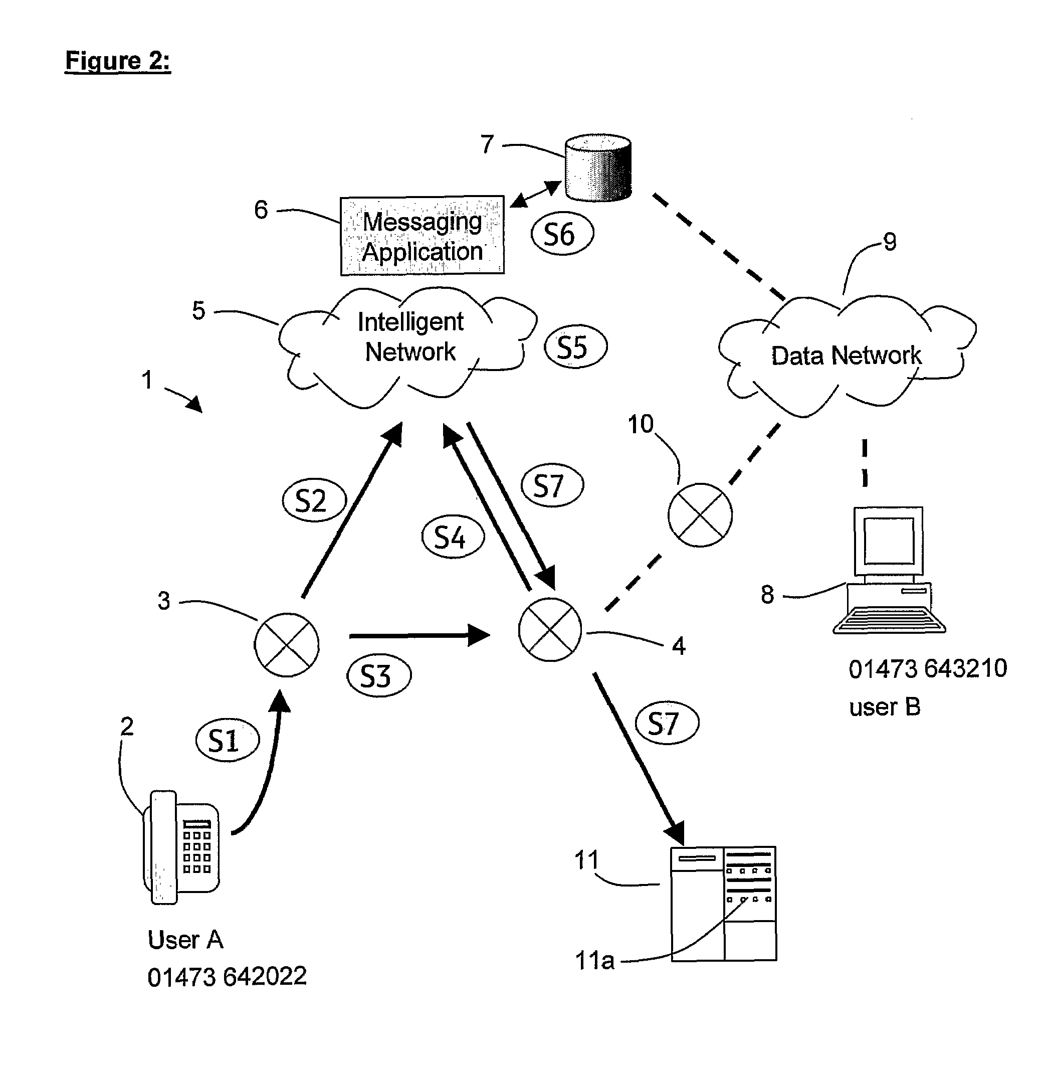
[0055]Whilst FIG. 2 showed a first example of a system in which a first user can send an audio-visual communication directly to the mailbox of a second user, FIG. 7 shows an alternative arrangement of a system in which this can also be performed. FIGS. 6 and 7 show a procedure and communication system 20 in which a first user (A) of a communication device 2 can elect to send an audio-visual communication directly to a mailbox 21a of a second user (B). User A's telephone 2 is connected in a conventional manner to a public switched telephone network (PSTN) via a digital local exchange (DLE) 23. The PSTN network comprises a multiplicity of exchanges as is conventionally known in the art, but for clarity only one other is illustrated in FIG. 7, DLE 24.

[0056]In step S20, user A decides they would like to leave a voice mail message for user B and uses telephone 2 to dial a three digit prefix [171] followed by the telephone number [01473 643210] they would usually dial to reach user B. The...

third embodiment

[0059]Whilst FIGS. 2 and 7 showed first and second examples respectively of systems in which a first user can send an audio-visual communication directly to the mailbox of a second user, FIG. 9 shows a further alternative system in which this can be performed. FIGS. 8 and 9 show a procedure and communication system 30 in which a first user (A) of a communication device 2 can elect to send an audio-visual communication directly to a mailbox 31a of a second user (B). User A's telephone 2 is connected in a conventional manner to a public switched telephone network (PSTN) via a digital local exchange (DLE) 33. The PSTN network comprises a multiplicity of exchanges as is conventionally known in the art, but for clarity only one other is illustrated in FIG. 7, DLE 34.

[0060]In step S30, user A decides they would like to leave a voice mail message for user B and uses telephone 2 to dial a three digit prefix [171] followed by the telephone number [01473 643210] they would usually dial to rea...


PUM


Abstract

A communication system (1) in which a user (A) can elect to leave a message directly in the mailbox (11a) of another user (B) without calling or disturbing user (B). A store (database 7) is generated and maintained which identifies those users who are allowed direct access to the mailbox of user (B). The store is automatically updated whenever user (B) sends a communication to other users.

Description

[0001]This application is the U.S. national phase of international application PCT / GB2004 / 005205 filed 10 Dec. 2004 which designated the U.S. and claims benefit of GB 0328758.8, dated 11 Dec. 2003, the entire content of which is hereby incorporated by reference.[0002]The present invention relates generally to telecommunications systems, and in particular to systems in which a user can elect to leave an audio-visual message directly in the mailbox of the called subscriber.[0003]Within the field of audio-visual communication, a system may be designed such that a subscriber (user) can choose not to telephone or make a video call which disturbs another user, but can instead elect to leave a voicemail (or videomail) message which the other user can collect when convenient. This is particularly useful when it is known that the other user is likely to want to not be disturbed (for example because it is very late at night) or because they do not want to bother the user with a social telepho...

Claims


Application Information

Patent Timeline
Patent Type & Authority Patents(United States)
IPC IPC(8): H04M1/64H04M3/38H04M3/436H04M3/53H04M3/533
CPCH04M3/38H04M3/53316H04M3/4211H04M3/42059
Inventor CLIFT, DAVID JJOHNSTON, JOHN GCLAXTON, ROBERT MBORTHWICK, DAVID J
Owner BRITISH TELECOMM PLC
Learn More