
Sensor controller

a technology of sensor controller and controller, applied in the field of sensor controller, can solve the problems of stylus not being able to detect the uplink signal, need to be improved, and the uplink signal may fail

Active Publication Date: 2019-10-15
WACOM CO LTD
View PDF18 Cites 8 Cited by
  • Summary
  • Abstract
  • Description
  • Claims
  • Application Information

AI Technical Summary

Benefits of technology

[0007]Therefore, according to one aspect of the present invention, a sensor controller is provided that can prevent a situation in which a stylus cannot detect an uplink signal due to a change in the ground potential of the stylus caused by the uplink signal.
[0009]Therefore, according to another aspect of the present invention, a sensor controller is provided that can prevent an uplink signal from affecting the operation of another apparatus.
[0012]Various embodiments of the present invention facilitate preventing the predetermined AC signal (uplink signal) from changing the ground potential of the stylus, which in turn facilitate preventing the situation in which the stylus cannot detect the uplink signal due to the change in the ground potential.
[0013]According to a further aspect of the present invention, the AC signal (uplink signal) may be prevented from appearing in the electrodes of another apparatus, such as a display apparatus, which in turn facilitates preventing the uplink signal from affecting the operation of another apparatus.

Problems solved by technology

However, the detection of the uplink signal may fail in the detection method, and the method needs to be improved.
As a result, the stylus cannot detect the uplink signal.
As a result, contents of display of the display apparatus may be disturbed.
Similarly, the uplink signal is also detected on each of electrodes of other apparatuses, such as a speaker, a near field communication (NFC) communication apparatus, a complementary metal-oxide semiconductor (CMOS) camera, and a wireless local area network (LAN) antenna, arranged near the panel surface, and the operations of the apparatuses may be disturbed.

Method used


Image

  • Sensor controller
  • Sensor controller
  • Sensor controller

Examples


Embodiment Construction

[0037]Embodiments of the present invention will now be described in detail with reference to the attached drawings.

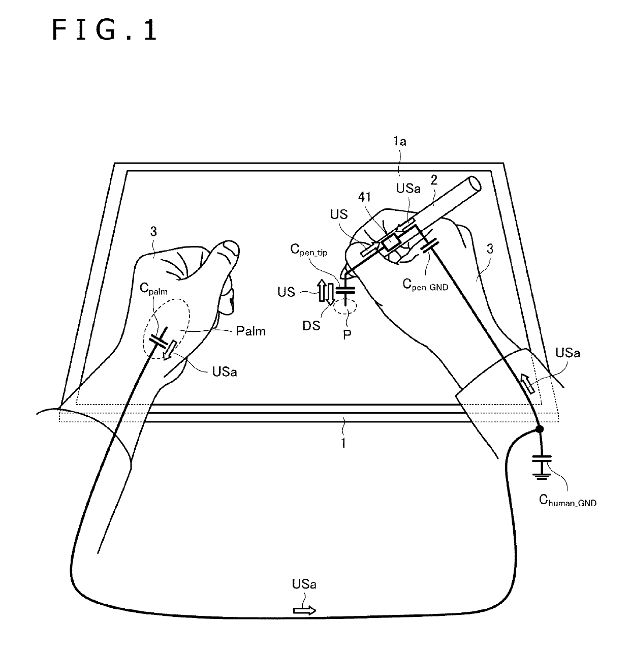
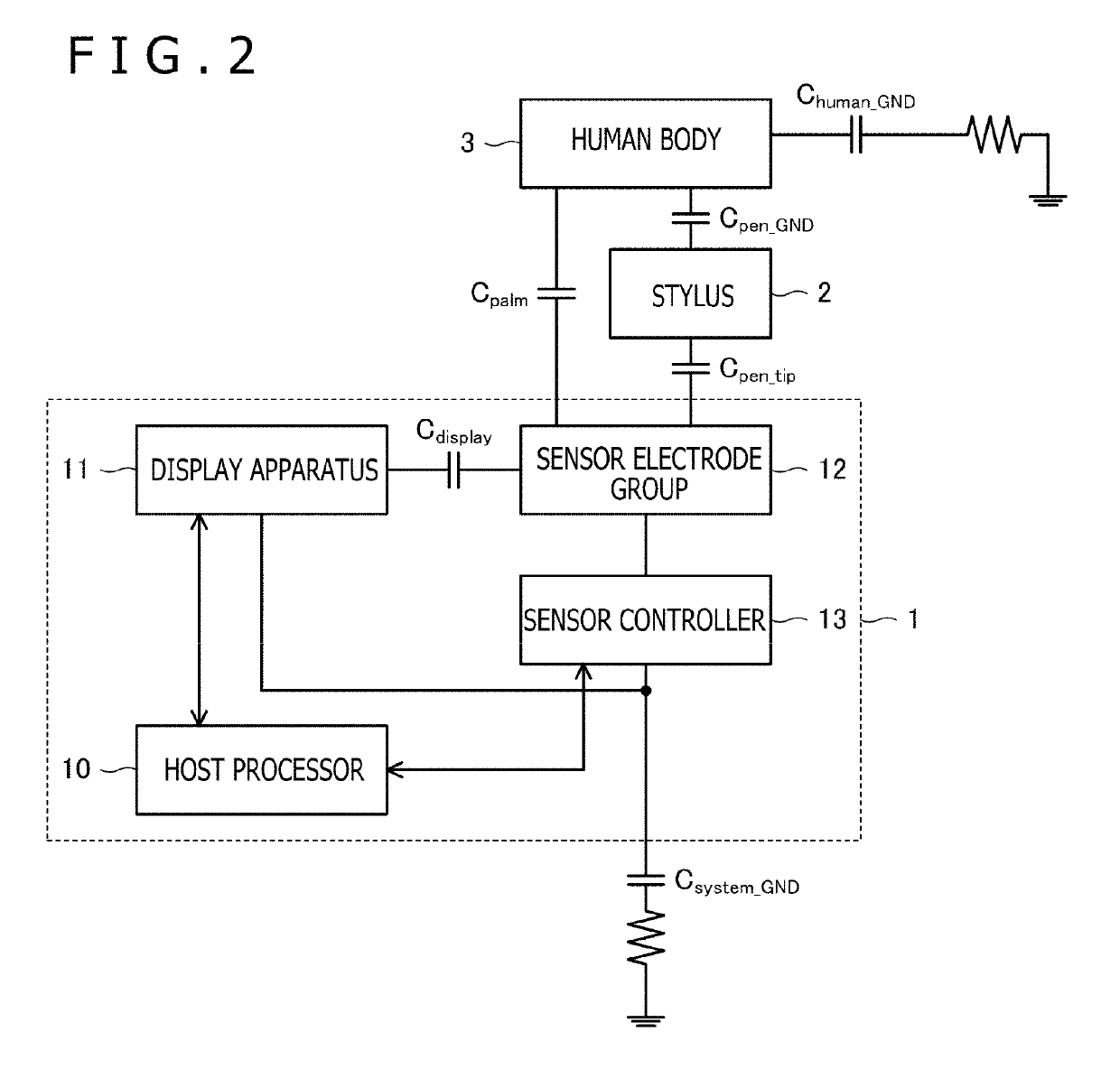
[0038]FIG. 1 depicts a use state of a tablet terminal 1 and a stylus 2 according to a first embodiment of the present invention. FIG. 2 depicts an internal configuration of the tablet terminal 1 illustrated in FIG. 1 and an equivalent circuit of the tablet terminal 1 and the stylus 2. An outline of the present invention will be described first with reference to the drawings.

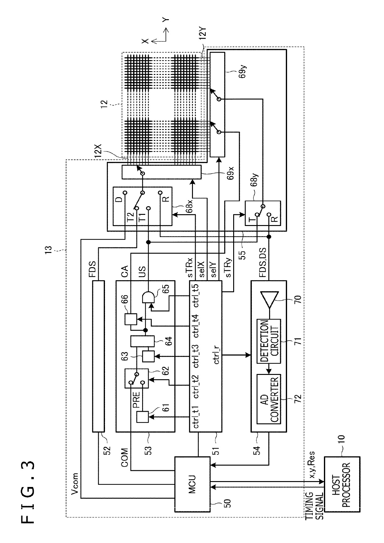
[0039]As illustrated in FIG. 2, the tablet terminal 1 includes a host processor 10, a display apparatus 11, a sensor electrode group 12, and a sensor controller 13. Among these, the host processor 10 is a processor that controls the entire tablet terminal 1, and operations of the components in the tablet terminal 1 described later are executed under the control of the host processor 10.

[0040]The display apparatus 11 is a display that can display arbitrary information according to the control of the h...


PUM


Abstract

A sensor controller is provided, to be connected to a sensor electrode group configuring a surface. The sensor controller supplies a determined AC signal to one or more AC signal transmission electrodes that form part of a plurality of sensor electrodes included in the sensor electrode group, and the sensor controller transmits, from cancellation signal transmission electrode(s) different from the AC signal transmission electrodes, a cancellation signal configured to prevent a signal transmitted from the AC signal transmission electrodes from appearing in a ground terminal of a detection circuit of the stylus. The sensor controller thusly configured may facilitate preventing a situation in which the stylus cannot detect an uplink signal and facilitate preventing the uplink signal from affecting the operation of another apparatus such as a display apparatus.

Description

BACKGROUNDTechnical Field[0001]The present invention relates to a sensor controller, and particularly, to a sensor controller with a transmission function of an uplink signal.Description of the Related Art[0002]Among tablet terminals corresponding to pen input using a stylus, there is a tablet terminal in which a sensor controller that detects a position of the stylus can transmit an uplink signal to the stylus (for example, see WO 2017 / 029836 A1). The uplink signal is a signal for transmitting information from the sensor controller to the stylus, and the stylus executes a process, such as starting an operation and transmitting a pen signal, in response to the uplink signal.[0003]The sensor controller detects a pen signal to detect the stylus, and it is preferable to complete new detection (or discovery) of the stylus before the stylus touches a panel surface of sensor electrodes. Therefore, the stylus carries out a detection operation of the uplink signal even when the stylus is no...

Claims


Application Information

Patent Timeline
Patent Type & Authority Patents(United States)
IPC IPC(8): G06F3/0354G06F3/041G06F3/044G06F3/038
CPCG06F3/04162G06F3/041661G06F3/03545G06F2203/04104G06F3/044G06F3/0383G06F3/0418
Inventor KADOWAKI, JUNKOMATSU, HIDEYUKIHISANO, HARUHIKO
Owner WACOM CO LTD
Learn More