Transceiver System To Adapt to Antenna De-Tuning

a technology of transceiver and antenna, applied in the direction of transmitter monitoring, electrical equipment, transmission monitoring, etc., can solve the problems of large loss, and achieve the effect of reducing loss, improving performance, and improving performan

Active Publication Date: 2017-10-26
CHARLES STARK DRAPER LABORATORY
View PDF7 Cites 7 Cited by
  • Summary
  • Abstract
  • Description
  • Claims
  • Application Information

AI Technical Summary

Benefits of technology

[0008]The losses in a matching network are related to the ratio of the impedances being matched. In general, a higher the ratio results in a larger loss. In the described embodiments, the first tuning technique (adjusting the tunable antenna) operates to manipulate the antenna to exhibit a feedpoint impedance that is close enough to the receiver's input impedance to ensure good receiver performance. The resulting antenna impedance significantly reduces the impedance matching ratio that the second tuning technique (i.e., the tunable matching network) must accommodate.
[0009]A lower impedance ratio reduces the loss in the transmit path, which maximizes transmitted power. Reducing losses also extends the life of the energy storage device (e.g., battery) powering the transceiver, since less energy is wasted through the losses. Another benefit of the lower ratio is a reduction in the complexity and physical space requirements (i.e., size) of the matching network components.
[0010]The described embodiments utilize an E-field probe along with other tuning components, all embedded in the antenna, to perform the required tuning detection for both transmit and receive operations. This configuration eliminates the losses and bulk associated with components associated with conventional tuning detection devices.
[0011]The losses that are incurred when matching two impedances increase non-linearly as the real-part impedance ratio increases. By using the tunable matching network directly on the output of the transmitter's power transistor, the fixed matching network is eliminated, thereby reducing size, loss and parts count. The described embodiments trade off variations in the reflection loss against the variations in matching insertion loss, to find a tuning solution that always maximizes the RF power delivered to the antenna, consistent with a desired DC power consumption.
[0012]In one aspect, the invention may be a method of adapting an antenna to a transceiver system having a receiver subsystem and a transmitter subsystem. The method may comprise tuning the antenna with respect to the receiver subsystem using an automatic tuning system, to result in an optimal receive signal at the receiver subsystem in response to RF energy radiated to the antenna. After tuning the antenna with respect to the receiver subsystem, the method may further comprise tuning a tunable matching network, coupled between an output of an RF power device of the transmitter subsystem and an input of the antenna, to facilitate an optimal power transfer amount from the RF power device to the antenna while the RF power device operates according to one or more desired parameters.

Problems solved by technology

In general, a higher the ratio results in a larger loss.

Method used


Image

  • Transceiver System To Adapt to Antenna De-Tuning
  • Transceiver System To Adapt to Antenna De-Tuning
  • Transceiver System To Adapt to Antenna De-Tuning

Examples


Embodiment Construction

[0030]A description of example embodiments of the invention follows.

[0031]The teachings of all patents, published applications and references cited herein are incorporated by reference in their entirety.

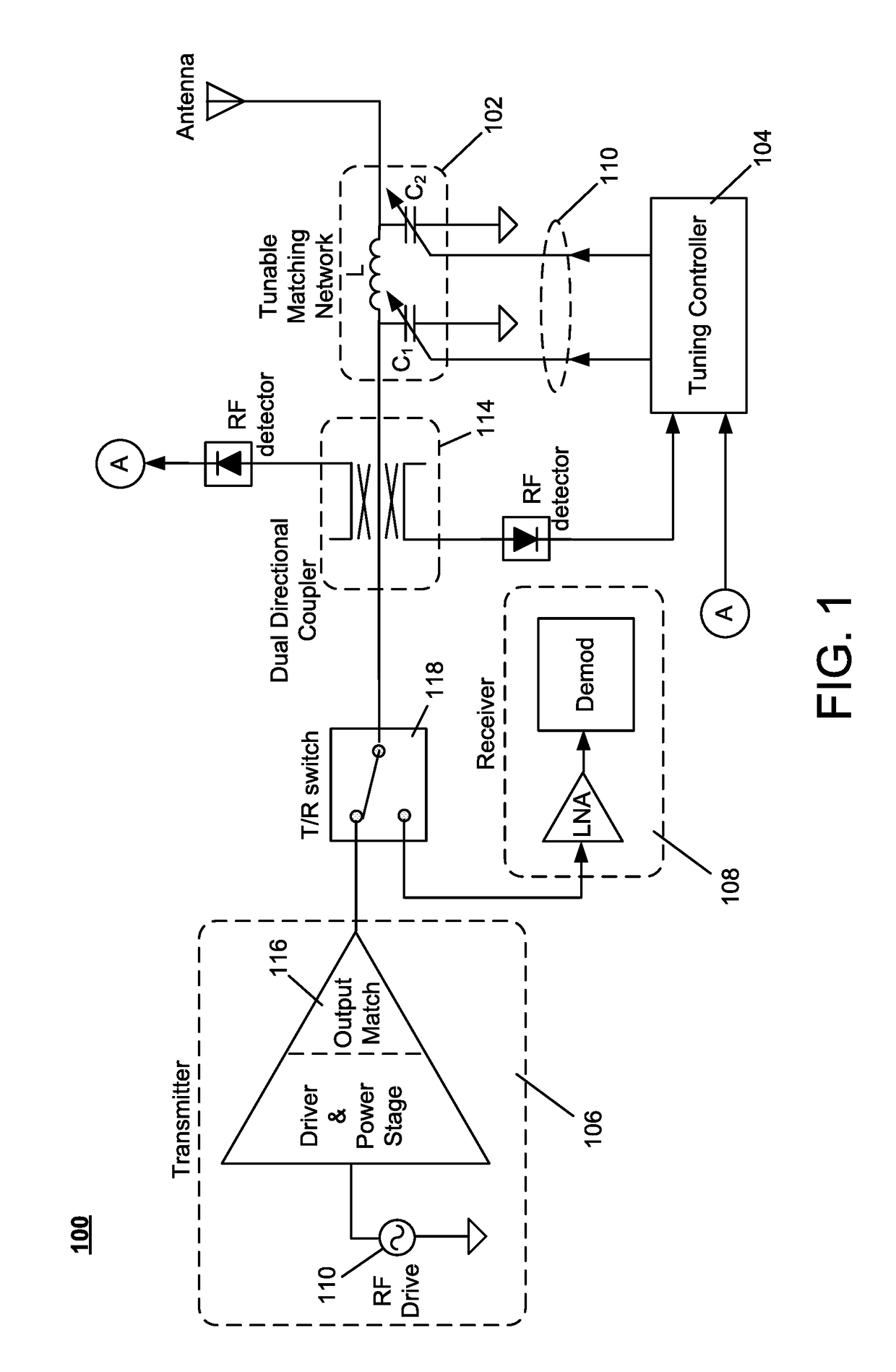
[0032]FIG. 1 illustrates a block diagram of a conventional transceiver system 100, with a tunable matching network 102, configured to monitor and minimize reflected power. Elements of the tunable matching network 102 are electrically manipulated by a tuning controller 104 to present a specific impedance (e.g., 50Ω) to the transmitter 106 and the receiver 108 of the transceiver system 100, while compensating for impedance variations at the antenna feedpoint due to antenna detuning effects. The tuning controller 104 generates the control signals 110 based on forward and reverse power, sensed by RF detectors 112, of propagating RF energy coupled from the RF path by a dual directional coupler 114. The tuning controller manipulates the elements of the matching network 102, through the con...


PUM


Abstract

A method of adapting an antenna to a transceiver system having a receiver subsystem and a transmitter subsystem comprises using an automatic tuning system to tune the antenna with respect to the receiver subsystem. The tuning results in an optimal receive signal at the receiver subsystem in response to RF energy radiated to the antenna. The tuning system may include a tuning detection element for radiating RF energy to the antenna, and a tuning element for tuning the antenna. After tuning the antenna, the method further comprises tuning a tunable matching network, coupled between an output of an RF power device of the transmitter subsystem and an input of the antenna, to facilitate an optimal power transfer amount from the RF power device to the antenna while the RF power device operates according to certain desired parameters. The desired parameters may include output power and efficiency.

Description

RELATED APPLICATIONS[0001]This application claims the benefit of U.S. Provisional Application No. 62 / 346,033, filed on Jun. 6, 2016; U.S. Provisional Application No. 62 / 326,375, filed on Apr. 22, 2016; and is a continuation-in part of U.S. application Ser. No. 15 / 456,430, filed on Mar. 10, 2017. The entire teachings of the above applications are incorporated herein by reference.GOVERNMENT SUPPORT[0002]This invention was made with government support under CON02458-1 awarded by the Defense Advanced Research Projects Agency (DARPA). The government has certain rights in the invention.BACKGROUND[0003]An RF transmitter / receiver (transceiver) may be electrically coupled to an antenna to transmit and receive electromagnetic radiation. The electrical coupling can be designed to create a conjugate impedance match between the transceiver and the antenna, which maximizes the power transfer between the transceiver and the antenna. In a controlled environment, the antenna input impedance remains ...

Claims


Application Information

Patent Timeline
Patent Type & Authority Applications(United States)
IPC IPC(8): H04B1/04H04B1/14H04B1/40H04B17/10
CPCH04B1/0458H04B1/40H04B2001/045H04B17/102H04B1/14H04B1/18H04B5/0037
Inventor WHITE, DOUGLAS W.DAVIS, SETH M.
Owner CHARLES STARK DRAPER LABORATORY
Why Eureka
Try Eureka