Wavelength tunable laser and method of controlling the same

a tunable laser and wavelength technology, applied in the direction of laser details, semiconductor lasers, optical resonator shape and construction, etc., can solve the problem of exceedingly difficult control to avoid discontinuity

Inactive Publication Date: 2006-01-05
FUJITSU LTD
View PDF10 Cites 10 Cited by
  • Summary
  • Abstract
  • Description
  • Claims
  • Application Information

AI Technical Summary

Benefits of technology

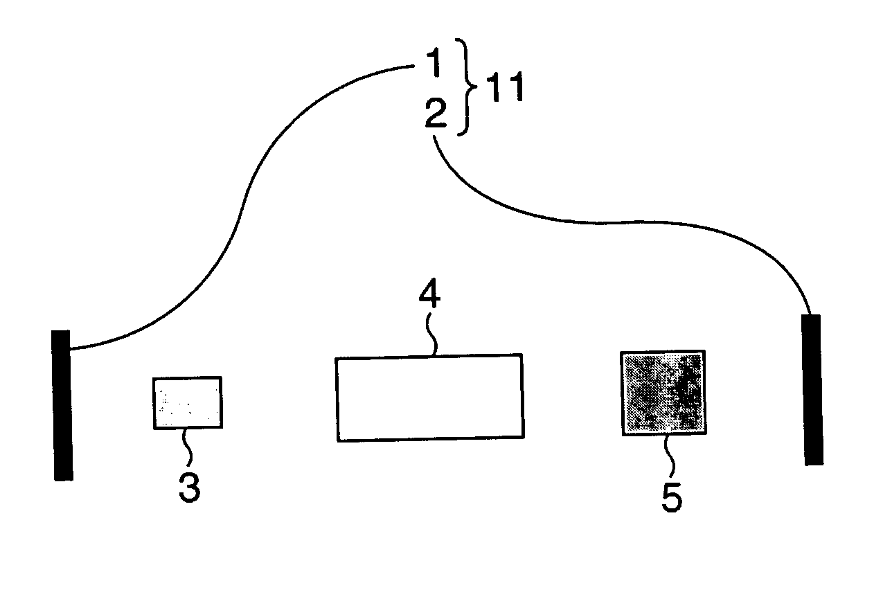
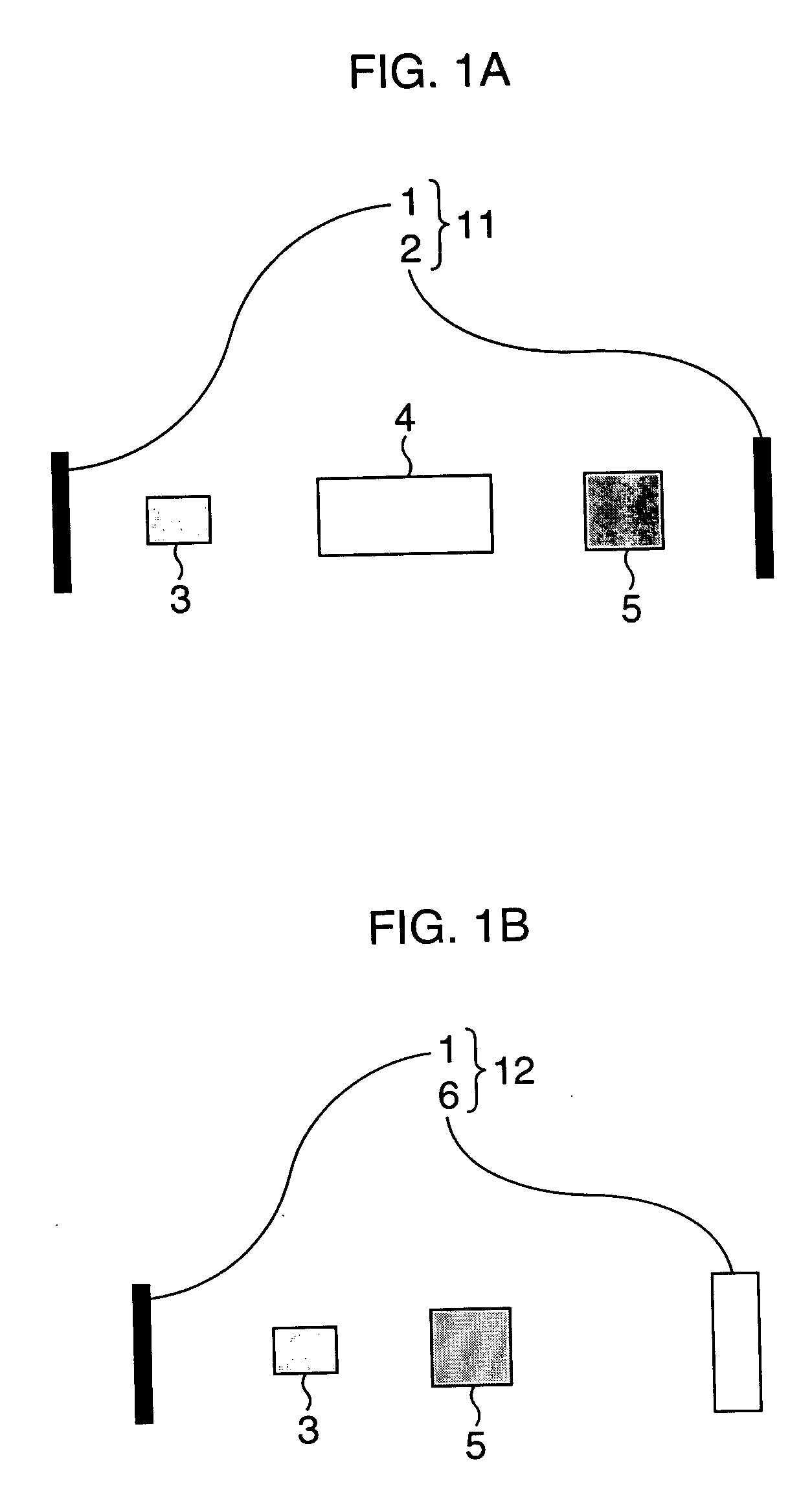
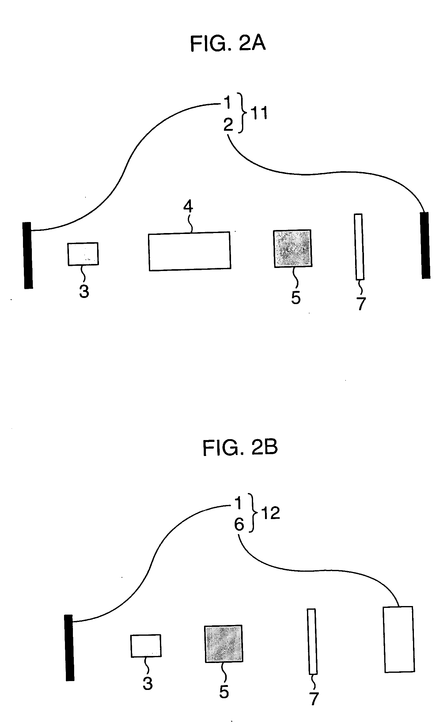
[0023] A method for controlling a wavelength tunable laser in the present invention is performed using the wavelength tunable laser including a resonator, an optical amplifier provided inside the resonator, radiating a laser beam, a wavelength tunable filter provided inside the resonator or as one part of the resonator, allowing an oscillation wavelength to be tunable, and a phase controller controlling a phase of the laser beam resonating inside the resonator, in which the wavelength tunable filter has an asymmetric filter characteristic and is designed so that a loss given to a long wavelength side with respect to the peak wavelength of the filter is larger than a loss given to a short wavelength side, so that the oscillation wavelength of the laser beam from the optical amplifier is allowed to coincide with the peak wavelength of the filter in the wavelength tunable filter.

Problems solved by technology

Therefore, the control should be performed, avoiding the discontinuity, however, the control avoiding the discontinuity is exceedingly difficult because a tolerance of control is narrow due to the approach of the discontinuity to the optical output power peak wavelength.

Method used


Image

  • Wavelength tunable laser and method of controlling the same
  • Wavelength tunable laser and method of controlling the same
  • Wavelength tunable laser and method of controlling the same

Examples


first embodiment

[0058] In this embodiment, a specific example of a wavelength tunable laser including a transmission-type wavelength tunable filter having an asymmetric filter characteristic.

[0059] FIGS. 8 are schematic diagrams showing a principal structure of a transmission-type wavelength tunable laser according to the first embodiment.

[0060] As shown in FIG. 8A, the transmission-type wavelength tunable laser includes a semiconductor optical amplifier (SOA) 21 radiating a laser beam, an acousto-optic wavelength tunable filter (AOTF) 22 as being a transmission-type wavelength tunable filter having an asymmetric filter characteristic, a lens 23 condensing the laser beam, an etalon 24 as being an optical element having a cyclic transmissive wavelength, and a reflector 25.

[0061] The SOA 21 has an end surface 21a which is a cleavage surface functioning as a reflector, and a resonator 31 is formed between the end surface 21a and the reflector 25. As the SOA 21, for example, one of the SOAs using a ...

second embodiment

[0071] In this embodiment, a specific example of a wavelength tunable laser including a reflection-type wavelength tunable filter having an asymmetric filter characteristic will be described.

[0072] FIGS. 10 are schematic diagrams showing a principal structure of a reflection-type wavelength tunable laser according the second embodiment.

[0073] The reflection-type wavelength tunable laser is a so-called 3-electrode DBR (distribution Bragg reflection-type mirror) laser in which a filter characteristic of a DBR unit is asymmetric. The DBR unit can change a reflection wavelength thereof by injecting a electric current.

[0074] The wavelength tunable laser is constituted by including an active layer unit 41, a phase control unit 42, and the DBR unit 43 as shown in FIG. 10A. An electrode 41a is pattern-formed on an upper surface of the active layer unit 41, an electrode 42a is pattern-formed on an upper surface of the phase control unit 42 and an electrode 43a is pattern-formed on an uppe...


PUM


Abstract

A wavelength tunable laser is constituted by including a resonator composed of a pair of reflectors arranged to face each other, and inside the resonator, a SOA radiating a laser beam with a gain for a wide range of wavelengths, a transmission-type wavelength tunable filter having an asymmetric filter characteristic, and a phase controller controlling a phase of the laser beam resonating inside the resonator.

Description

CROSS-REFERENCE TO RELATED APPLICATIONS [0001] This application is based upon and claims the benefit of priority from the prior Japanese Patent Application No. 2004-195879, filed on Jul. 1, 2004, the entire contents of which are incorporated herein by reference. BACKGROUND OF THE INVENTION [0002] 1. Field of the Invention [0003] The present invention relates to a wavelength tunable laser of which an oscillation wavelength is tunable and a method of controlling the same. [0004] 2. Description of the Related Art [0005] Along with dramatic increase in demands for communication in recent years, development of multi-wavelength communication systems (wavelength division multiplexing (WDM) systems), which realize high-capacity transmission by a single optical fiber by way of multiplexing plural single beams of different wavelength, shows progress. For such a wavelength division multiplexing system, a wavelength tunable laser capable of selecting a desired wavelength from a wide range of wa...

Claims


Application Information

Patent Timeline
Patent Type & Authority Applications(United States)
IPC IPC(8): H01S3/10
CPCH01S5/141H01S3/106
Inventor TAKABAYASHI, KAZUMASANAKAZAWA, TADAONAKAZAWA, YUMISHIRAISHI, TAKASHI
Owner FUJITSU LTD
Why Eureka
Try Eureka