
Toner conveying device and image forming apparatus including the toner conveying device

a conveying device and toner technology, applied in the direction of electrographic process equipment, instruments, optics, etc., can solve the problems of unstable toner supply and affecting the quality of toner supplied from a toner container to a developing device, etc. problem

Inactive Publication Date: 2005-07-12
RICOH KK
View PDF23 Cites 37 Cited by
  • Summary
  • Abstract
  • Description
  • Claims
  • Application Information

AI Technical Summary

Benefits of technology

The present invention relates to a device for conveying toner in an image forming apparatus. The device includes a toner container, a device for urging the discharge of toner, a mechanism for conveying toner through a path, and a device for detecting the amount of toner flow. The invention also includes a control device that adjusts the toner discharge based on the detection of toner flow. The technical effect of this invention is to improve the accuracy and stability of toner conveyance, resulting in better quality images.

Problems solved by technology

In the image forming apparatus including such a toner conveying device, an amount of toner supplied from a toner container to a developing device tends to be unstable depending on the condition of the toner in the toner container.
Specifically, toner tends to be not easily discharged from the toner container due to the agglomeration of toner and the decrease of fluidity of toner caused by the moisture absorption of the toner.
Therefore, the amount of toner supplied from a toner container to a developing device typically decreases in a relatively high humidity environment.
When the amount of toner supplied from the toner container to the developing device becomes unstable, image quality deteriorates.
If a large amount of toner remains in a used toner container when replacing the used toner container, the remaining toner is unnecessarily disposed of, thereby increasing the operating expense of the image forming apparatus, and harming the environment.
However, if a sensor is provided in a disposable toner container, the cost of the toner container increases.
The above-described problems may occur not only in a toner conveying device in an image forming apparatus that conveys toner from a toner container to a developing device, but also in any types of powder conveying device that conveys powder from a powder container to a desired device.
However, in the former method, in addition to a toner removing device, a drive device that drives the toner removing device needs to be provided, thereby increasing the cost of the apparatus.
Further, the location of the toner removing device is limited in an image forming apparatus.
In the latter method, a detection error may be caused when a greater than expected amount of toner is adhered to the detection surface of the detecting device.
Further, the latter method cannot be applied to a toner container which is replaced after a relatively long period.

Method used


Image

  • Toner conveying device and image forming apparatus including the toner conveying device
  • Toner conveying device and image forming apparatus including the toner conveying device
  • Toner conveying device and image forming apparatus including the toner conveying device

Examples


Embodiment Construction

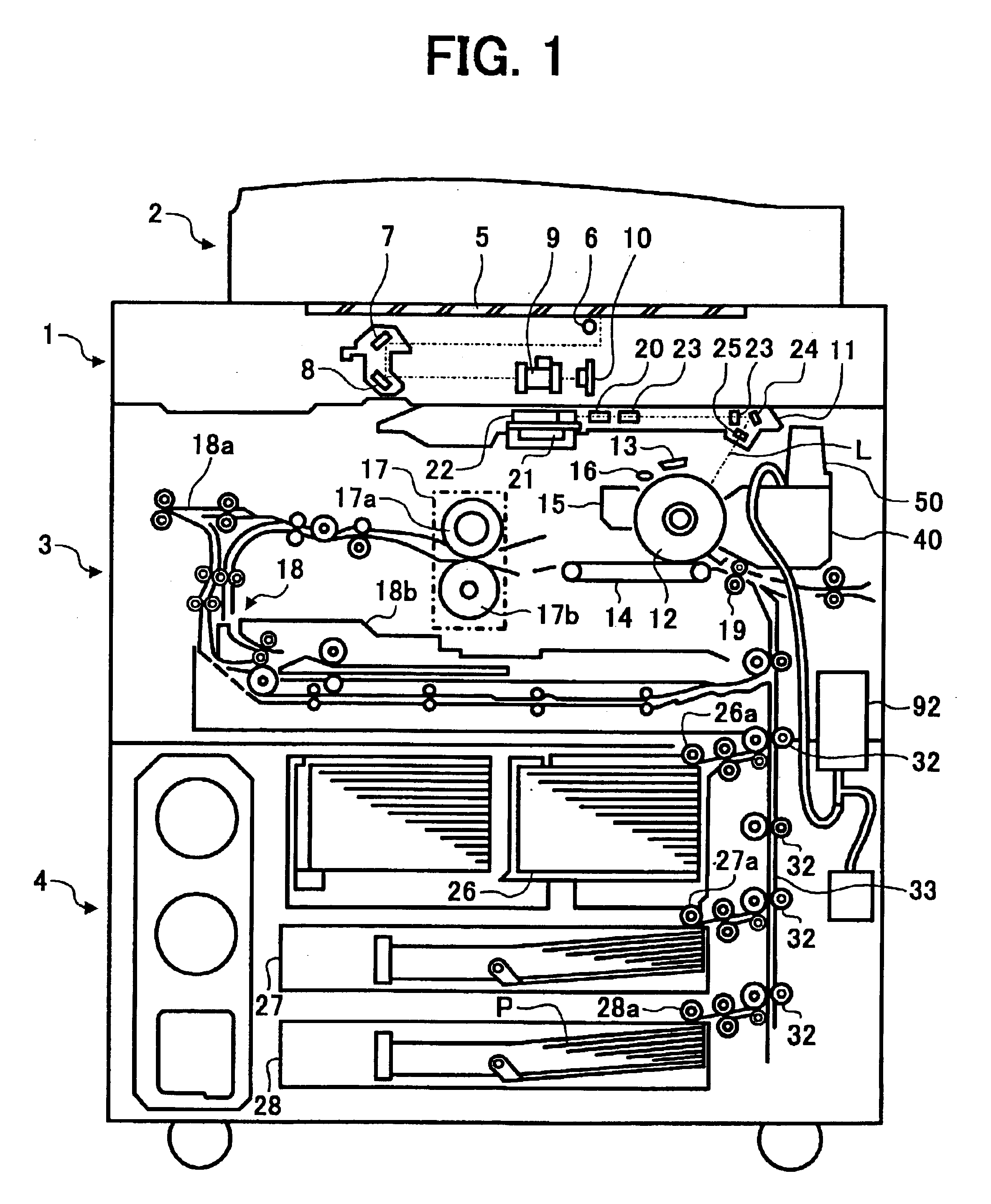
[0038]Preferred embodiments of the present invention are described in detail referring to the drawings, wherein like reference numerals designate identical or corresponding parts throughout the several views. In the preferred embodiments, the present invention is applied to, for example, an electrophotographic copying machine (hereafter simply referred to as a “copying machine”) as an image forming apparatus. The image forming apparatus of the present invention may be any type of image forming apparatus, for example, a copying machine, printer, facsimile machine, etc. or a multi-functional image forming apparatus, in which images including one or more colors are formed on a transfer material. First, a basic construction of the copying machine according to the present embodiment will be described.

[0039]FIG. 1 is a schematic view of a construction of a main part of the copying machine according to the embodiment of the present invention. As illustrated in FIG. 1, the copying machine i...


PUM


Abstract

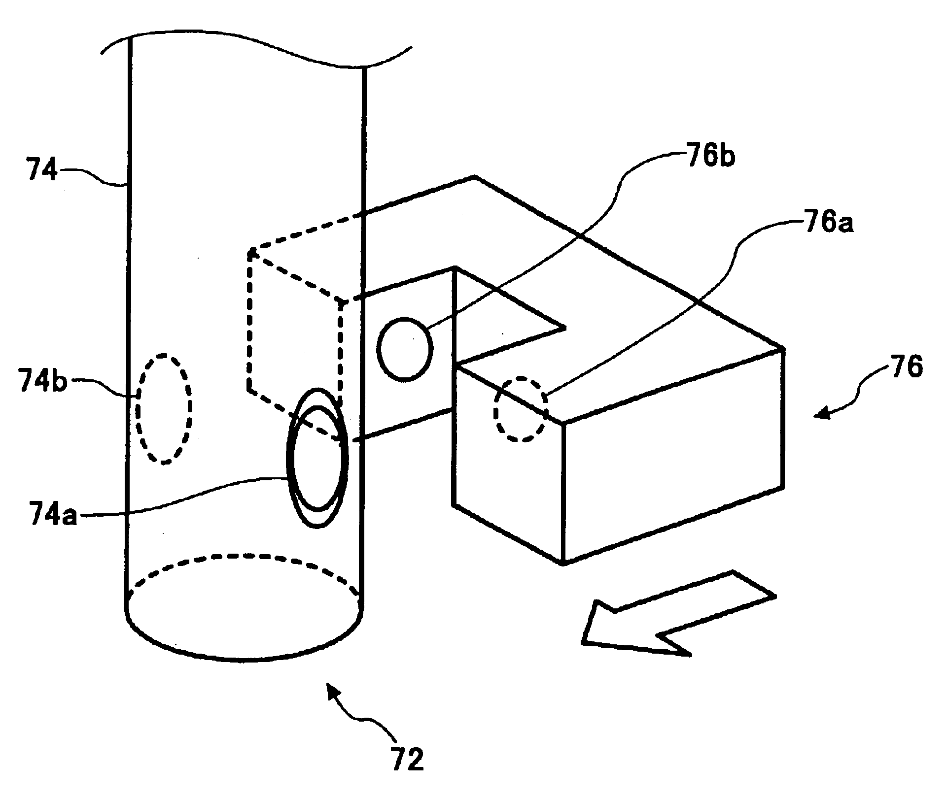
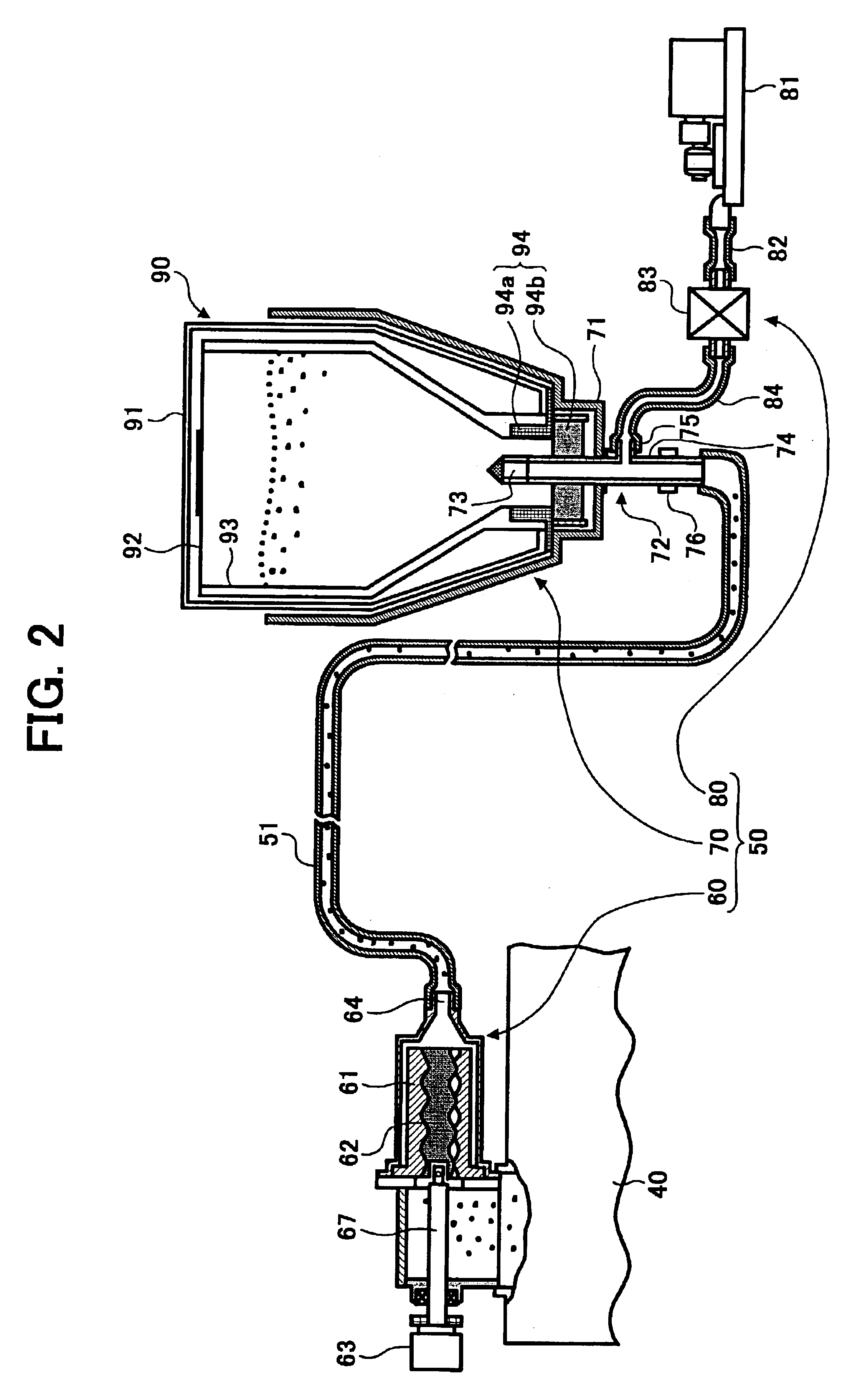
A toner conveying device includes a toner container that contains toner, a toner discharge urging device that urges the discharge of the toner from the toner container, a toner conveying mechanism that conveys the toner discharged from the toner container through a toner conveying path member, and a flow amount detecting device that detects the flow amount of the toner conveyed in the toner conveying path member.

Description

CROSS-REFERENCE TO RELATED APPLICATIONS[0001]The present application claims priority to Japanese Patent Application No. 2002-161113 filed in the Japanese Patent Office on Jun. 3, 2002 and Japanese Patent Application No. 2002-276021 filed in the Japanese Patent Office on Sep. 20, 2002, the disclosures of which are hereby incorporated herein by reference.BACKGROUND OF THE INVENTION[0002]1. Field of the Invention[0003]The present invention relates to a toner conveying device that conveys toner from a toner container to a developing device in an image forming apparatus such as a copying machine, a printer, a facsimile machine, or other similar image forming apparatus.[0004]2. Discussion of the Background[0005]An image forming apparatus such as a copying machine, a facsimile machine, a printer, or other similar image forming apparatus that forms images by use of a powder-shaped developer, such as toner, and a two-component developer including toner and magnetic carrier, has been widely u...

Claims


Application Information

Patent Timeline
Patent Type & Authority Patents(United States)
IPC IPC(8): G03G15/08
CPCG03G15/0848G03G15/0874G03G15/0879G03G15/0877
Inventor FUJIMORI, KOHTAHATTORI, YOSHIO
Owner RICOH KK
Learn More