Automatic injection device

a technology of automatic injection and injection device, which is applied in the field of contrast medium injection device, can solve the problems of complex valve switching operation, poor device configuration balance, and sometimes forgotten switching operation

Inactive Publication Date: 2005-07-12
NEMOTO KYORINDO KK
View PDF9 Cites 55 Cited by
  • Summary
  • Abstract
  • Description
  • Claims
  • Application Information

AI Technical Summary

Benefits of technology

[0012]The present invention has been devised in order to solve such a problem and it is an object of the present invention to provide an automatic injection device mountable with a plurality of syringes, in which when at least one head is in a state of injection and at least one head is in a stopped state, the backward-moving of the cylinder piston of the stopped head is prevented so as to prevent liquid from undesirably being mixed and the amount thereof from unreliably being injected.
[0014]According to the present invention, when the syringe piston mounted at the second head is in a stopped state, even if the piston holder is moved forward for the injection of a chemical solution in the syringe at a the first head, the backward-moving of the syringe piston at the second head can be prevented. Therefore the chemical solution in the syringe of the first head does not flow into the syringe of the second head, thereby the mixture of the chemical solution can effectively prevented.

Problems solved by technology

However, when a manually operable valve is used for this purpose, the switching operation of the valves is complicated and the switching is sometimes forgotten.
Although it is possible to perform the switching of the valves automatically and electrically, it is not preferable to provide a drive unit of such a switching in the midway through a substantially soft and light tube because the balance of the device configuration become worse.
On the other hand, if a one-way valve is used, the device can be made simple and compact, but the backward-moving action of the syringe piston cannot be performed.
Although an idea can be also conceived that a pressure in the forward direction is applied to the syringe piston at the head B so as to resist the pressure from the side of the head A when the syringe piston at the head B is in a stopped state, the axis of rotation of the motor continues to be in a stopped state while electricity is being supplied to the motor, and there arises a problem of the seizing of the motor.

Method used


Image

  • Automatic injection device
  • Automatic injection device
  • Automatic injection device

Examples


Embodiment Construction

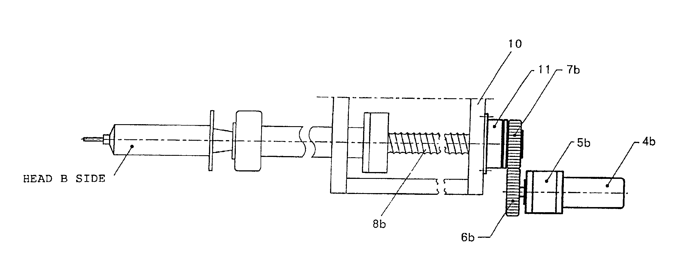
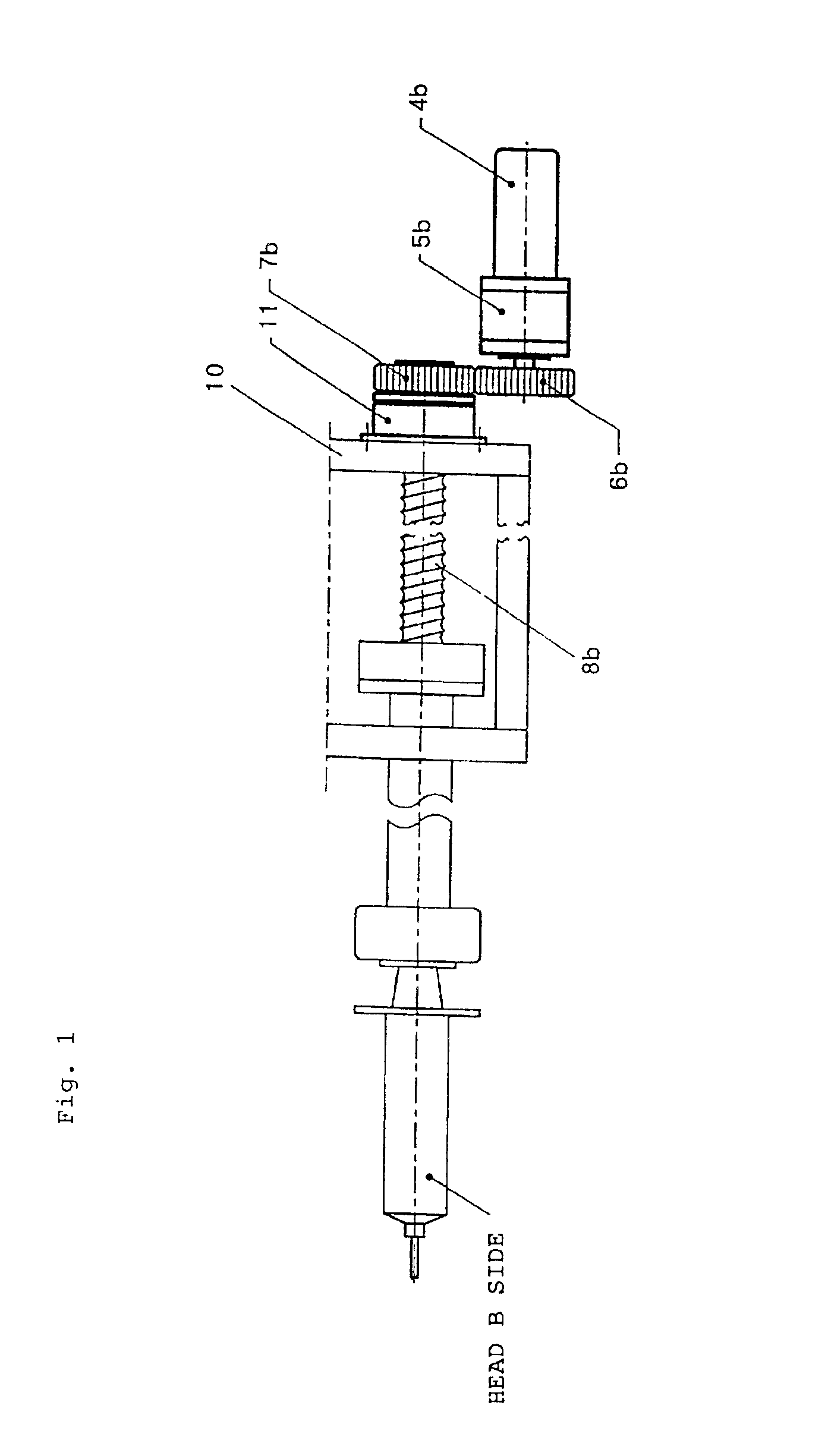
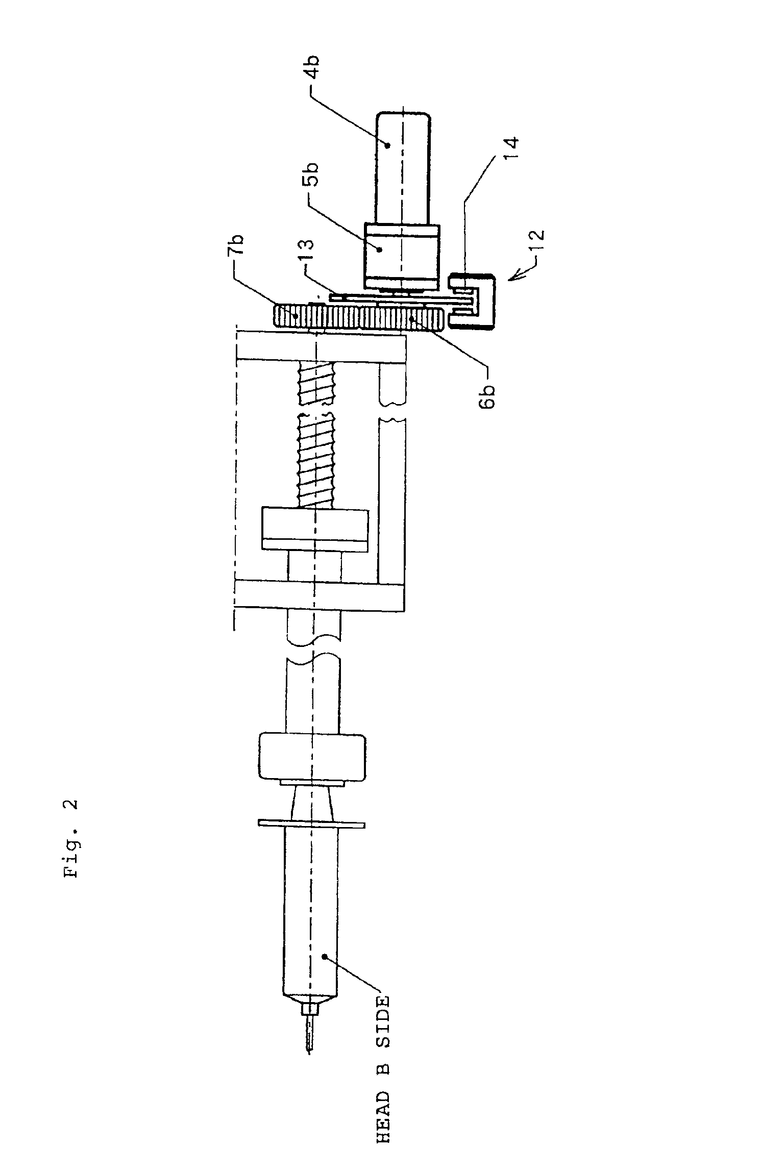
[0052]In general, in order to move a piston holder forward and backward, the above-described drive mechanism of the automatic injection device converts the rotational movement of a motor into a linear movement by using a ball screw and the like, as,described by reference to FIG. 9. Hence, backward-moving prohibition mechanism can be provided in any portion of a transfer route from the motor to the piston holder. That is, depending on the specific embodiment of the invention, the backward-moving prohibition mechanism can be constituted such that either the rotation is prohibited or the linear movement is prohibited.

[0053]Referring to a double head type chemical solution injection device mountable with two syringes, a description will be made below. As shown in FIG. 9, the syringe for a contrast medium is mounted on one side of a head A and the syringe for a physiological saline solution is mounted on the other side of a head B. In the same drawings described below, though only the he...


PUM


Abstract

An automatic injection device has piston holders holding cylinder pistons and plural systems of heads having a drive mechanism for moving the piston holders forward and backward so that the device can hold a plurality of syringes and operates injection or suction in each syringe independently. This device also has a mechanism for prohibiting the backward-moving of the piston holder of a second head when the piston holder of a first head is in a forward-moving state and the piston holder of the second head is in a stopped state. This structure effectively prevents liquid from being undesirably mixed and the injection amount thereof from becoming less accurate.

Description

BACKGROUND OF THE INVENTION[0001]1. Field of the Invention[0002]The present invention relates to a contrast medium injection device used for X-ray CT image diagnosis, MRI image diagnosis and the like.[0003]2. Description of the Related Art[0004]A contrast medium is used for the diagnosis of X-ray CT (computed tomography) images, MRI, angio-images (angiographic images) and the like. The contrast medium is a liquid having high viscosity and the injection thereof by means of a manual power takes a lot of time and labor so that in recent years automatic contrast medium injection devices have come to be used.[0005]An automatic injection device 100 of FIG. 8 is an example of such devices, and since it can be mounted with two syringes, it is referred to as a double-head type. FIG. 9 shows a typical mechanism of the automatic injection device. A syringe 1a for the contrast medium is set at the side of a head A, a syringe 1b for a physiological saline solution is set at the side of a head B,...

Claims


Application Information

Patent Timeline
Patent Type & Authority Patents(United States)
IPC IPC(8): A61M5/00A61M5/145A61M5/19A61B5/055A61M5/20A61B6/00A61M5/315A61M36/04
CPCA61M5/007A61M5/1456A61M5/19A61M5/2066A61M5/31501A61M5/31511A61M5/31575A61M5/31578A61M5/31596A61M2005/3152A61M2005/1403
Inventor FUKUDA, TAKASHI
Owner NEMOTO KYORINDO KK
Why Eureka
Try Eureka