Protective headgear system

a protective headgear and headgear technology, applied in the field of personal environmental protection systems, can solve the problems of cumbersome headgear units, clumsy headgear units, and long gowns or hoods that tend to become extremely cumbersome, and achieve the effects of convenient and snug attachment, easy and snug attachment, and easy attachment to the headgear structur

Inactive Publication Date: 2005-07-19
PABBAN DEVMENT
View PDF18 Cites 39 Cited by
  • Summary
  • Abstract
  • Description
  • Claims
  • Application Information

AI Technical Summary

Benefits of technology

[0012]The system also includes a removable and disposable filter which is adapted to be easily and snugly attached to the headgear structure to significantly cover the outer surface of the headgear structure. An optional, separate pre-filter may also be provided for mounting over the disposable filter.
[0013]A transparent facial shield (or lens) is adapted to easily attach to the headgear structure so as to cover the face of the wearer in order to maintain sterile, non-contaminating conditions for the wearer. An optional lens cover can be attached to the facial shield to protect the shield from abrasion caused by cleaning.
[0014]A flexible, closable cuff is adapted to be easily attached to the lower edge of the facial shield in order to enclose the lower projection of the lens and provide a seal about the wearer's head.

Problems solved by technology

In some instances, the air filters are built into the helmet structure and produce a rather clumsy, cumbersome headgear unit.
The hose-connected systems, and the long gowns or hoods tend to become extremely cumbersome as well as restrictive of the movements and flexibility of the wearer during a procedure.
This structure tends, therefore, to become costly inasmuch as the disposable filtration devices are quite expensive.
Moreover, these systems tend to be fairly expensive, especially regarding the disposable portions of the system.

Method used


Image

  • Protective headgear system
  • Protective headgear system
  • Protective headgear system

Examples


Embodiment Construction

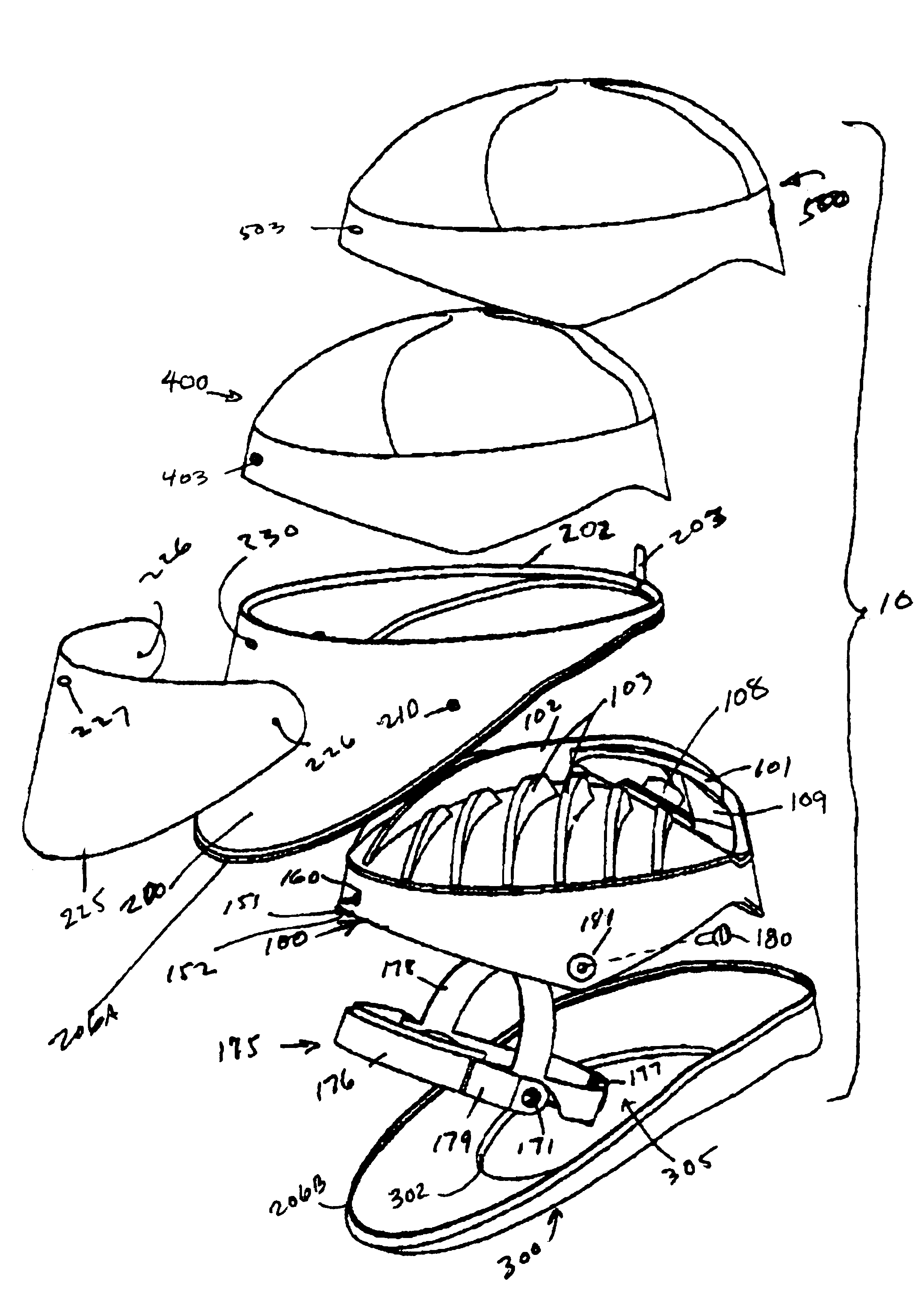
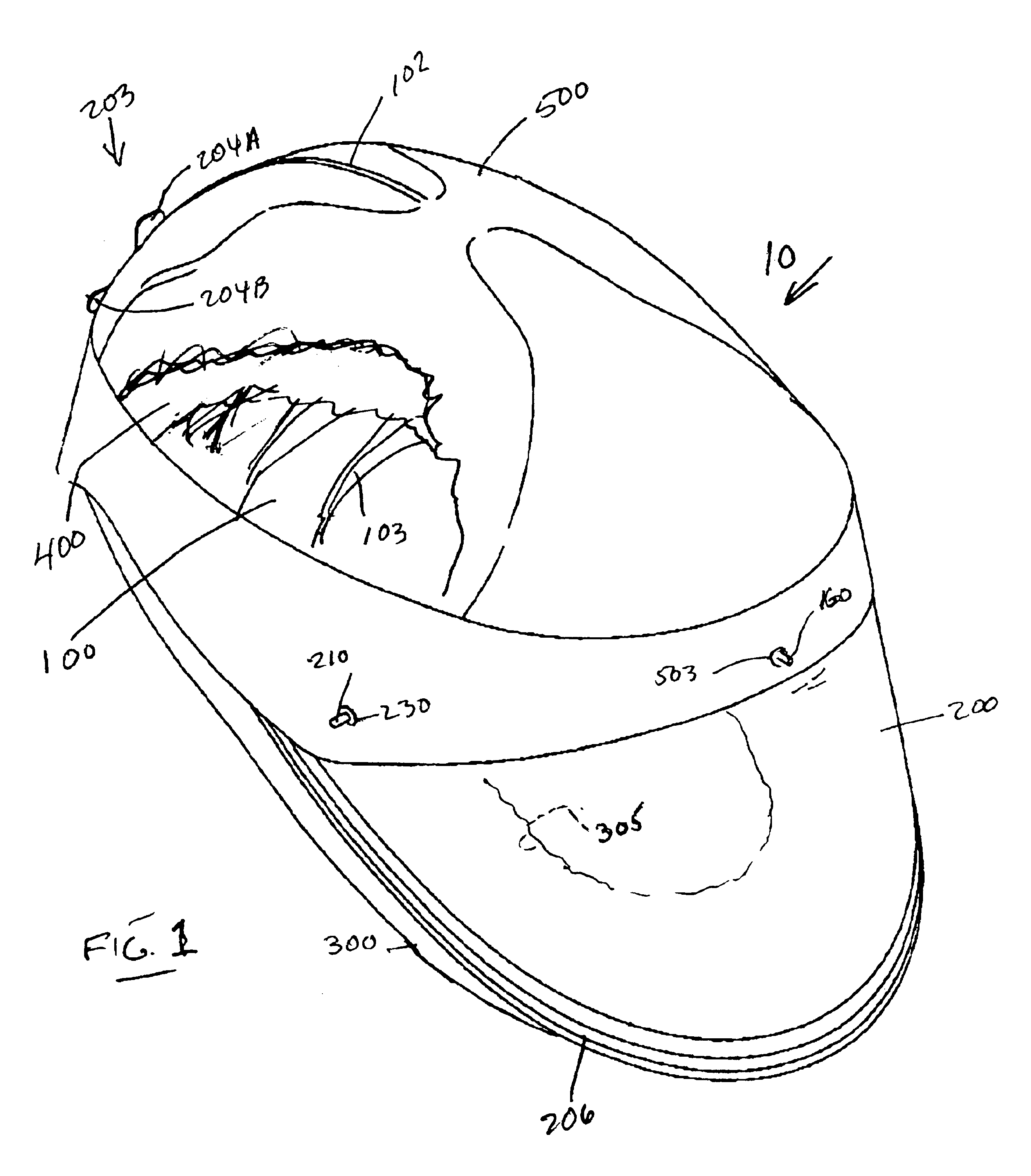
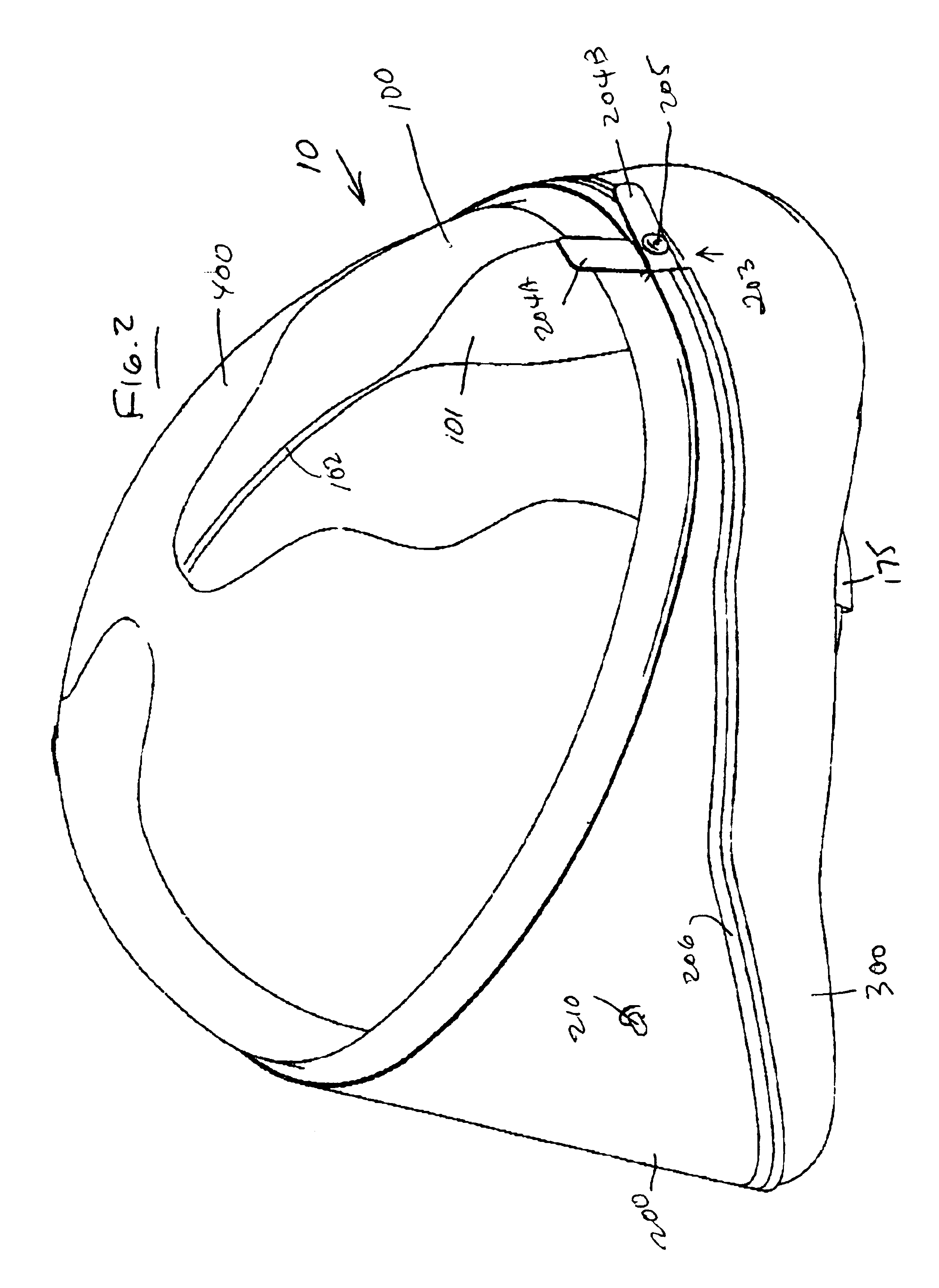
[0021]Referring to all of the Figures concurrently, there is shown one embodiment of the helmet assembly 10 of the instant invention. The helmet assembly 10 includes the helmet shell 100, the fan mechanism 108, the outer filter (or pre-filter) 500, the inner or main filter 400, the facial shield 200, the lens protector 225, the cuff 300, and the headband 175. An exploded view of the assembly 10 is shown in FIG. 5.

[0022]The helmet shell 100 (see FIGS. 1 and 5) is, typically, formed of a lightweight material, such as PETG or Polycarbonate, for example. Helmet shell 100 is configured to conform, generally, to the shape of the upper portion of the wearer's head but to be spaced away from the top of the head of the wearer by the headband 175 described infra.

[0023]In addition, as will be described infra, the helmet shell 100 is sufficiently sturdy so as to support a cooling or air moving mechanism 108, typically, e.g. a fan or the like.

[0024]A plurality of radial fins 103 extend upwardly ...


PUM


Abstract

This invention is directed to a protective headgear system which includes a relatively light weight, substantially rigid, headgear structure which may include an internal, adjustable headband. A fan mechanism is mounted on the headgear structure. A power supply selectively powers the fan. The system includes filter means which is attachable to the headgear structure to cover the structure. A facial shield is attachable to the headgear structure to cover the face of the wearer to maintain non-contaminating conditions relative to the wearer. A shield protector is attachable to the facial shield. A flexible cuff is attachable to the facial shield to enclose the lower opening of the lens and provide protection for the wearer.

Description

BACKGROUND[0001]1. Field of the Invention[0002]This invention is directed to personal environmental protection systems, in general, and, more particularly, to a headgear structure which is worn by an individual in an environment wherein control of filtered air and protection from particulate material is required.[0003]2. Prior Art[0004]There are several types of air flow, filtration and protective systems which are known in the art. Several types of such systems are currently available on the market for use in surgical arenas, in “clean room” environments, or in hazardous / contaminated environments.[0005]Some of the existing systems include hoods, gowns, filters, and the like. In some instances, the air filters are built into the helmet structure and produce a rather clumsy, cumbersome headgear unit. Known units frequently include external sources of air such as gas cylinders, air lines or the like which are connected to the helmet structure by tubes, hoses or the like. The hose-conn...

Claims


Application Information

Patent Timeline
Patent Type & Authority Patents(United States)
IPC IPC(8): A62B18/04A62B18/00A42B3/28A41D13/11A42B3/10A42B3/22A61B19/00A61F9/04
CPCA41D13/1153A42B3/10A42B3/226A62B18/045
Inventor GREEN, LAWRENCERIOS, OBEDMURILLO, CELESTINO
Owner PABBAN DEVMENT
Why Eureka
Try Eureka