Method and measuring instrument for determining the position of an edge of a pattern element on a substrate

a technology of pattern elements and measuring instruments, which is applied in the direction of instruments, optical radiation measurement, image enhancement, etc., can solve the problems of inability to reliably determine the position of the actual edges of the pattern element, the calculation of the straight-line fit already constitutes a considerable error in edge determination, and the fit can assume different values, etc., to achieve precise, rapid and reproducible measurements of the edge position

Inactive Publication Date: 2005-07-19
LEICA MICROSYSTEMS SEMICON GMBH
View PDF13 Cites 53 Cited by
  • Summary
  • Abstract
  • Description
  • Claims
  • Application Information

AI Technical Summary

Benefits of technology

[0014]It is therefore the object of the invention to describe a method for determining the position of an edge of a pattern element on a substrate which makes possible,

Problems solved by technology

Edge position determination is of particular significance because measurement errors have a direct impact on the production process.
The problem is that depending on the length of the fitted region and the consequently varying number of individual intensity profile values used for the straight-line fit, the fit can assume different slopes.
Calculation of the straight-line fit therefore already constitutes a considerable error in edge determination.
Another problem results from the fact that the measured curve shape of the intensity profile depends, among other facto

Method used


Image

  • Method and measuring instrument for determining the position of an edge of a pattern element on a substrate
  • Method and measuring instrument for determining the position of an edge of a pattern element on a substrate
  • Method and measuring instrument for determining the position of an edge of a pattern element on a substrate

Examples


Embodiment Construction

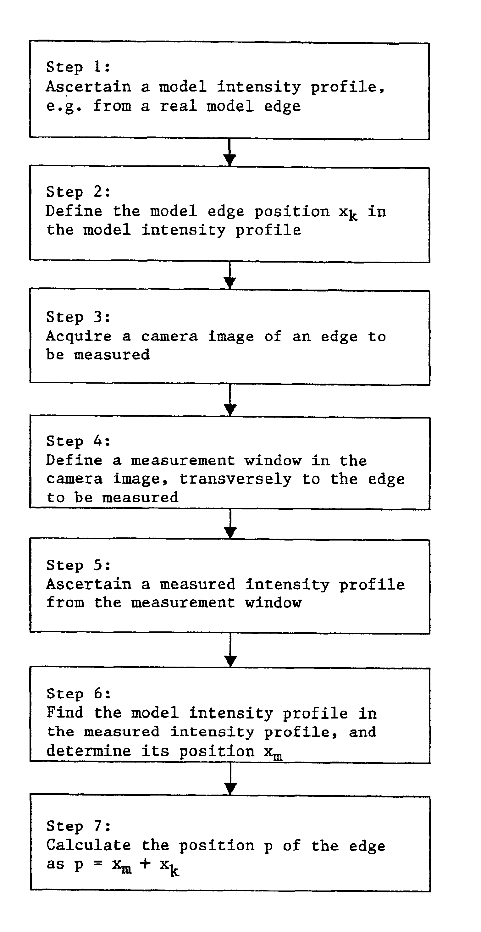
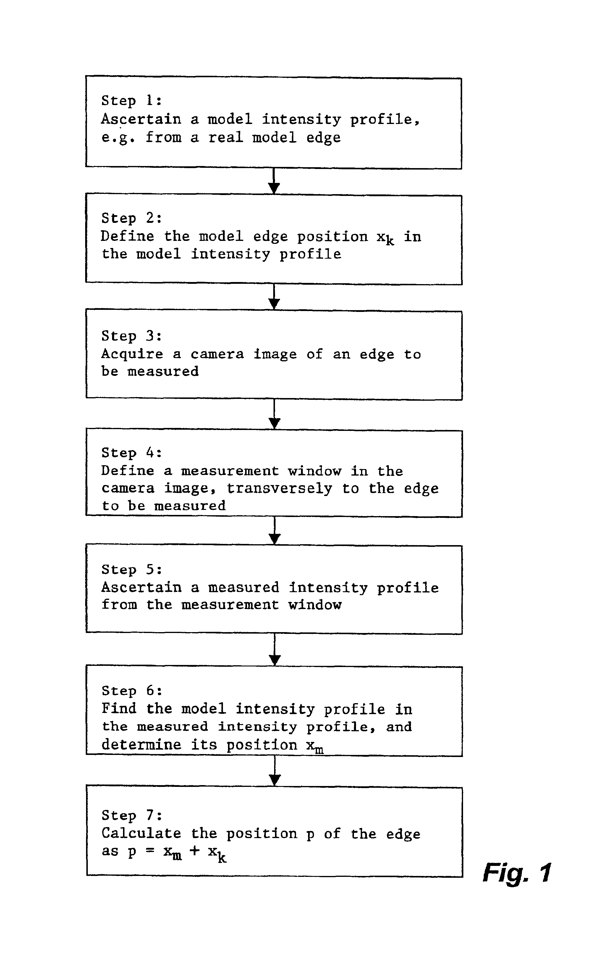
[0063]FIG. 1 shows a flow chart of the method according to the present invention. It comprises seven method steps that are described below.

[0064]In a first step of the method according to the present invention, a complete, nonlinear model intensity profile, which identifies the edge to be measured, of a model edge is ascertained and stored.

[0065]The model intensity profile can be ascertained in various ways.

[0066]One possibility is to measure an intensity profile of a real model edge and take a partial profile area of the measured intensity profile as the model intensity profile.

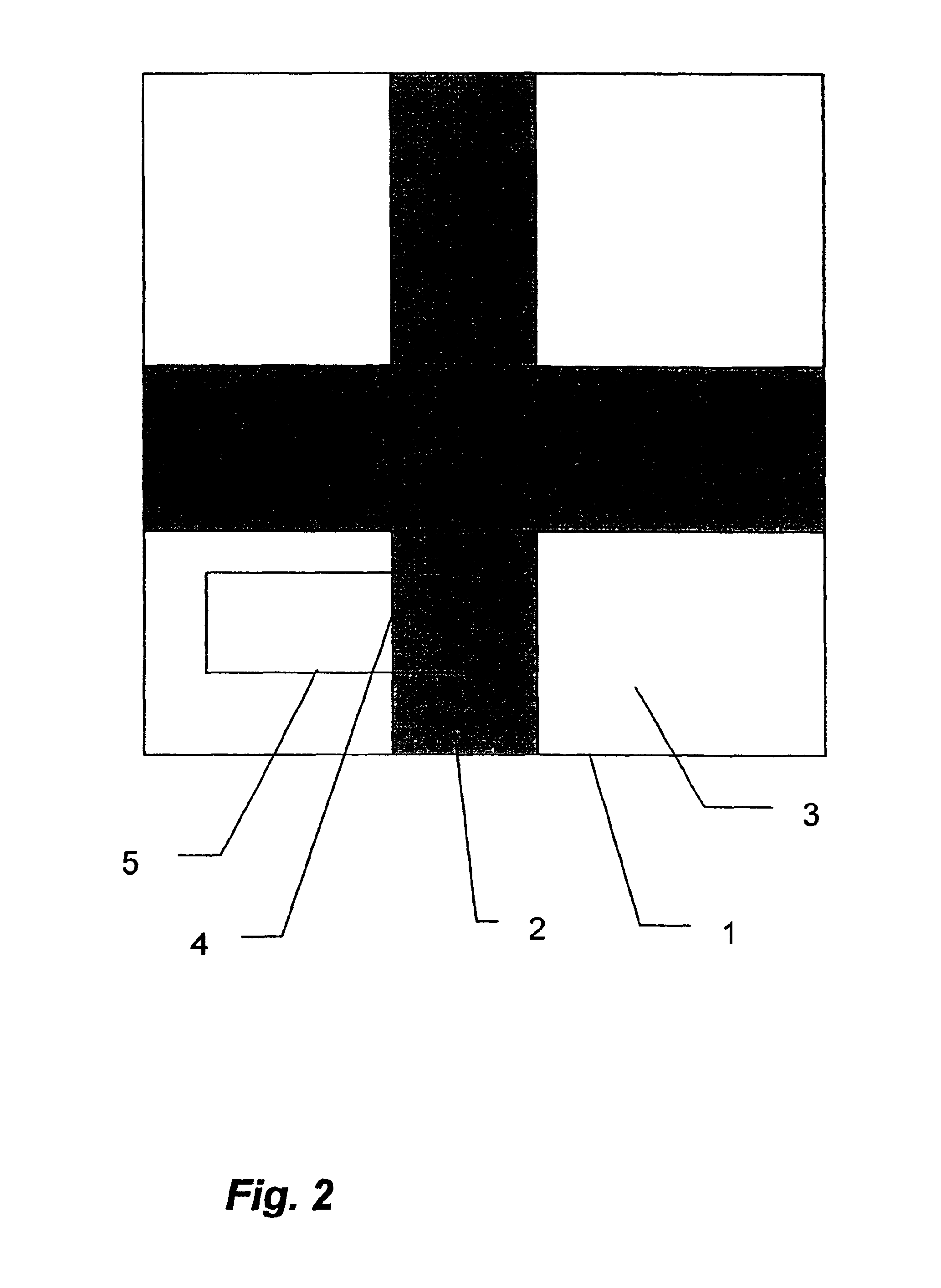
[0067]For that purpose, first a camera image, comprising pixels arranged in rows and columns, is acquired of a model substrate that comprises a model edge whose parameters correspond to those of the edges being measured. The optical measurement parameters used must be the same as those to be used subsequently upon measurement of the edge to be measured that is identifiable by way of the model edge. This ensu...


PUM


Abstract

A method and a measuring instrument for determining the position of an edge to be measured on a pattern on a substrate are described. A complete, nonlinear model intensity profile, which identifies the edge to be measured, of a model edge is ascertained and stored, and a desired edge position xk is defined therein with subpixel accuracy. A camera image of the substrate having the edge to be measured is acquired, and a one-dimensional measured intensity profile of the edge to be measured is determined therefrom. The model intensity profile is identified in the measured intensity profile with an indication of its location xm relative to a reference point. The desired position p of the edge to be measured is determined with subpixel accuracy as p=xm+xk.

Description

CROSS REFERENCE TO RELATED APPLICATIONS[0001]This invention claims priority of the German patent application 100 47 211.7-52 which is incorporated by reference herein.FIELD OF THE INVENTION[0002]The invention concerns a method and a measuring instrument for determining the position of an edge to be measured of a pattern element on a substrate, in which a one-dimensional measured intensity profile is ascertained from a camera image of the edge, and the position of the edge relative to a reference point is determined therefrom.BACKGROUND OF THE INVENTION[0003]The pattern elements to be measured are, in particular, opaque or transparent regions on mask surfaces or patterns on wafers that are used for semiconductor manufacture. The pattern elements to be measured have different widths and lengths and are distinguishable, for example, by way of the location, height, and orientation of their edges. In order to indicate the position of a pattern element on the substrate, often the mutually...

Claims


Application Information

Patent Timeline
IPC IPC(8): G06T7/00G01B11/00G01B11/03G06T7/73
CPCG06K9/4609G06T7/0046G06T2207/30148G06T7/75G06V10/443
Inventor RINN, KLAUSFRICKE, WOLFGANGWIENECKE, JOACHIM
Owner LEICA MICROSYSTEMS SEMICON GMBH
Why Eureka
Try Eureka