Fluid control valve

a technology of control valves and fluids, applied in the direction of valve details, valve arrangements, thin material handling, etc., can solve the problems of progressively harder to control the flow rate, progressively harder to manipulate the flow temperature, and difficult for the user to feel any difference in the two directions of motion or in a combination of those two directions, such as the vector produ

Inactive Publication Date: 2005-07-26
MASCO CORP
View PDF53 Cites 81 Cited by
  • Summary
  • Abstract
  • Description
  • Claims
  • Application Information

AI Technical Summary

Benefits of technology

[0017]Related objects and advantages of the present invention will be apparent from the following description.

Problems solved by technology

For example, the structure of this style and the mechanisms used to effect motion in the first and second directions make it progressively harder to manipulate flow temperature as the control valve approaches its full ON position.
It is also typically harder to control the flow rate as the temperature approaches either of the extreme positions (full hot or full cold) since the lever has usually rotated around to a less favorable position at these extremes as compared to the more optimized warm position.
Since the type two style does not decouple the motion or travel in a first direction from the motion or travel in a second direction, once the static friction on the ball is overcome, it is difficult for the user to feel any difference in the two directions of motion or in a combination of those two directions, such as the vector product.
Even if the user has selected one direction as his “preferred” direction of movement, it is difficult to sense or feel if there is any departure from the chosen path.

Method used


Image

  • Fluid control valve
  • Fluid control valve
  • Fluid control valve

Examples


Embodiment Construction

[0030]For the purposes of promoting an understanding of the principles of the invention, reference will now be made to the embodiments illustrated in the drawings and specific language will be used to describe the same. It will nevertheless be understood that no limitation of the scope of the invention is thereby intended, such alterations and further modifications in the illustrated device, and such further applications of the principles of the invention as illustrated therein being contemplated as would normally occur to one skilled in the art to which the invention relates.

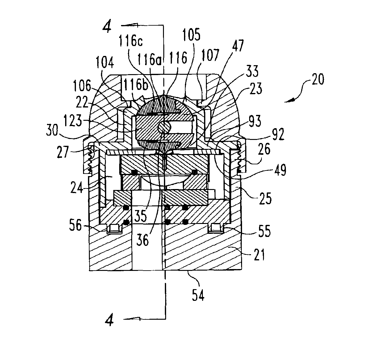
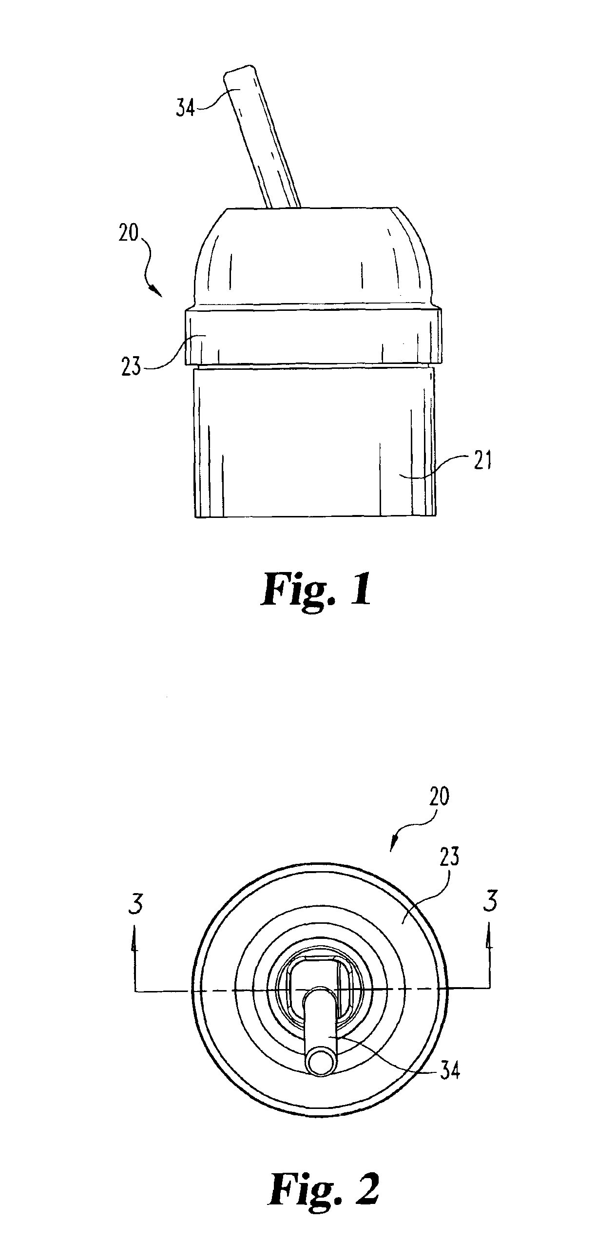
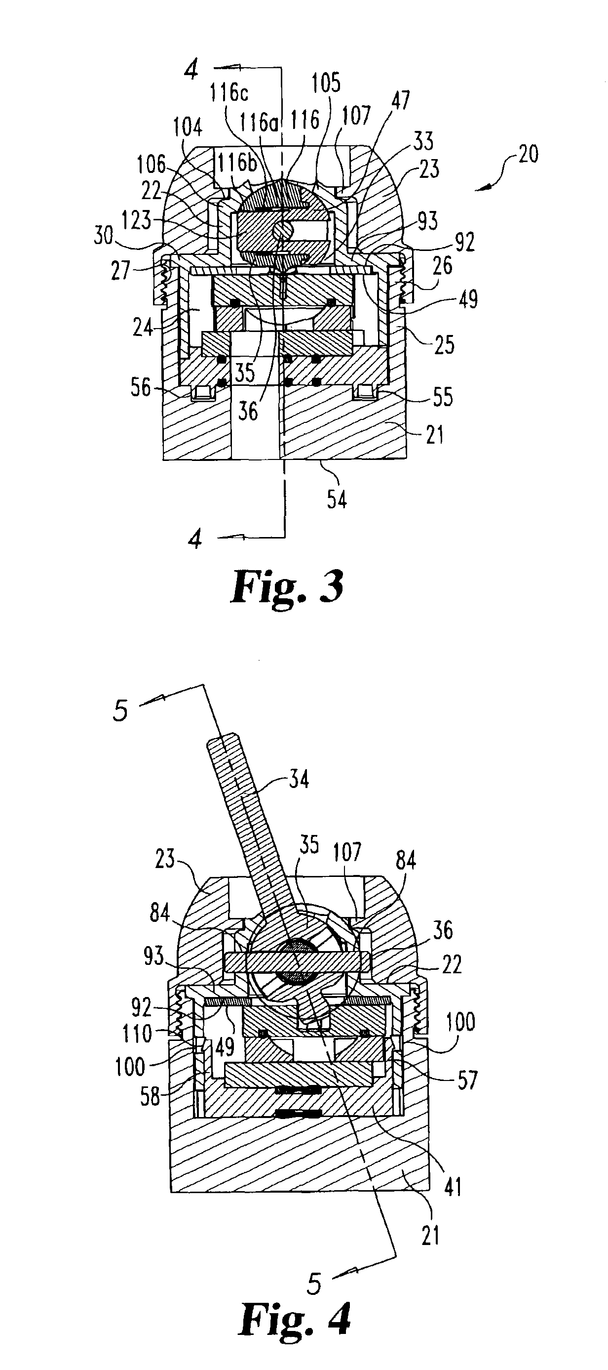
[0031]Referring to FIGS. 1-5, there is illustrated a fluid control valve 20 according to the present invention. Valve 20 includes as some of its primary structural component parts body 21, housing 22, and bonnet nut 23. These component parts are additionally illustrated in FIGS. 7 and 8. As illustrated, and as would be understood from a careful review of the specific structural features, a lower portion of hous...


PUM


Abstract

A fluid control valve for controlling the delivery of water includes a control lever that is movable in two directions by rotation of the lever about two independent axes. The fluid control valve includes a valve body assembly with flow passageways and a housing assembly attached to the valve body assembly to define an interior space. A flow control mechanism positioned in the interior space is constructed to enable movement of the lever about a first axis for translating rotational movement into sliding motion of an upper disk against a lower disk to adjust the water temperature. Rotation of the lever in a second direction translates rotational movement into sliding motion of the upper disk in a second direction to control the water flow rate. A drag spring positioned as part of the control mechanism changes the frictional force or feel between the two directions of lever movement.

Description

BACKGROUND OF THE INVENTION[0001]The present invention relates generally to fluid control valves that are constructed and arranged to control the delivery of fluid from a supply location to a use location. More specifically, the present invention relates to a water faucet control valve that is constructed and arranged to independently control the temperature of the water delivered to the use location and the flow rate of the water by a single handle or control lever or what can generally be referred to as a “joy stick”, due to its appearance, construction, range of motion, and degrees of freedom.[0002]Single-handled water faucet control valves are well known and have been offered with different mechanical arrangements for controlling the available directions of travel, the range of motion and the type or style of motion for the handle. Generally speaking, one style of control valve of the type being described includes a handle that is moved in a generally sideways (left-to-right and...

Claims


Application Information

Patent Timeline
Patent Type & Authority Patents(United States)
IPC IPC(8): F16K11/074F16K31/60F16K11/06
CPCF16K11/0746F16K31/605Y10T137/86549Y10T137/86823Y10T137/8708
Inventor HAENLEIN, HANS-CHRISTOPHRICHMOND, DOUGLAS SCOTT
Owner MASCO CORP
Why Eureka
Try Eureka