
Methods and apparatus for determining a direction of arrival in a wireless communication system

a wireless communication system and direction technology, applied in direction finders using radio waves, multi-channel direction-finding systems using radio waves, instruments, etc., can solve the problems of many mechanisms that induce array manifold errors, unstructured methods, and computational intensiveness of musi

Active Publication Date: 2005-07-26
GOOGLE TECH HLDG LLC
View PDF6 Cites 101 Cited by
  • Summary
  • Abstract
  • Description
  • Claims
  • Application Information

AI Technical Summary

Benefits of technology

The present invention relates to methods and apparatus for determining the direction of arrival (DOA) of a signal in a wireless communication system. The invention aims to improve the resolution of the DOA for a remote unit in a wireless communication system that utilizes an array of antennas. The invention addresses the issue of array distortions, which can cause degradation in the accuracy of DOA estimation. The invention provides methods that are resistant to array manifold distortions and are computationally efficient. The technical effects of the invention include improved accuracy in determining the location of a remote unit in a wireless communication system and improved performance of the wireless communication system.

Problems solved by technology

However, MUSIC is an unstructured method and therefore computationally intensive as each DOA estimate requires a full scan of the entire array manifold.
However, ESPRIT generally requires identical pairs of sensors, which makes it susceptible to many mechanisms that induce array manifold errors.

Method used


Image

  • Methods and apparatus for determining a direction of arrival in a wireless communication system
  • Methods and apparatus for determining a direction of arrival in a wireless communication system
  • Methods and apparatus for determining a direction of arrival in a wireless communication system

Examples


Embodiment Construction

[0015]The following detailed description of a preferred embodiment is merely exemplary in nature and is not intended to limit the invention or the application and uses of the invention.

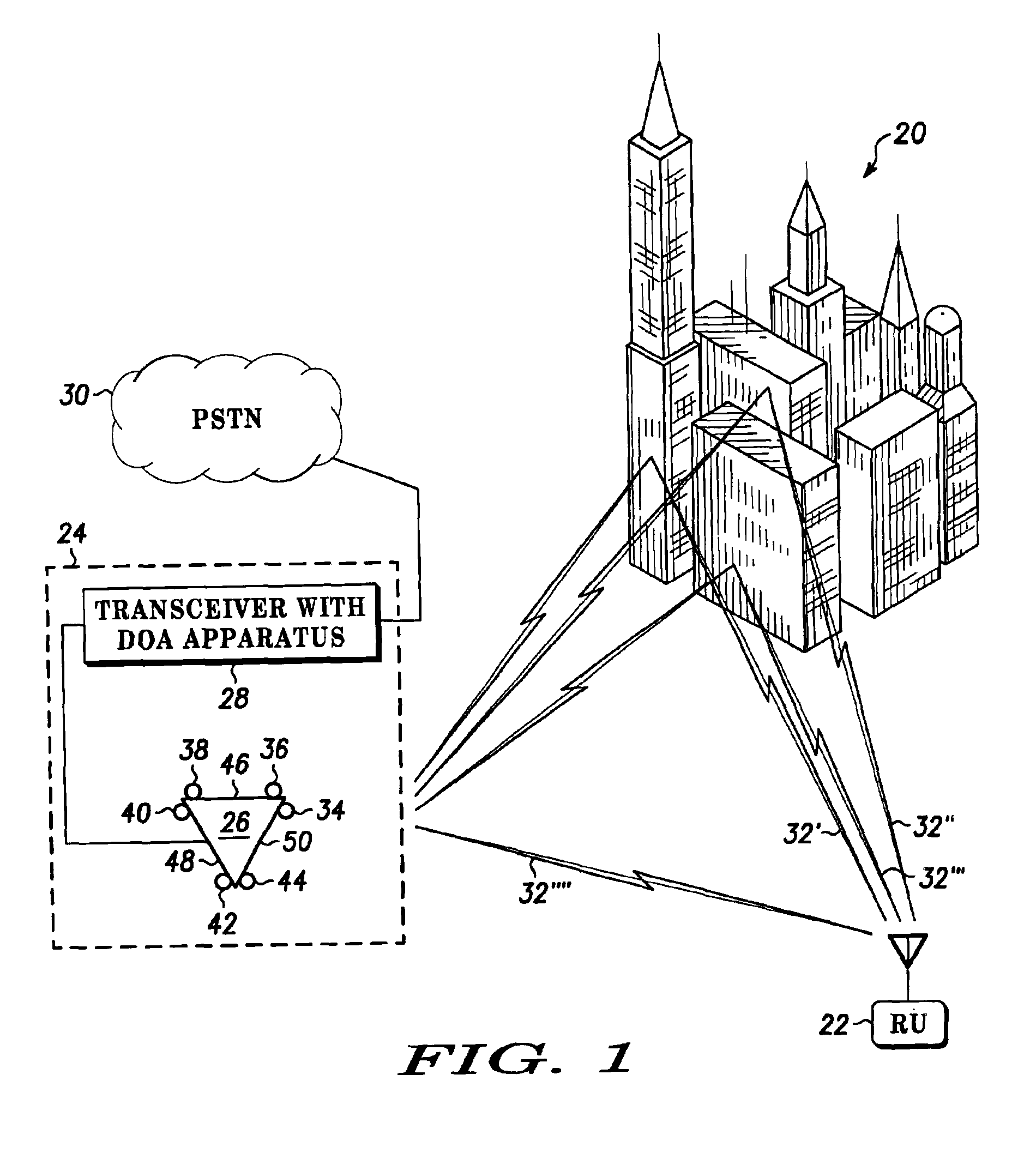
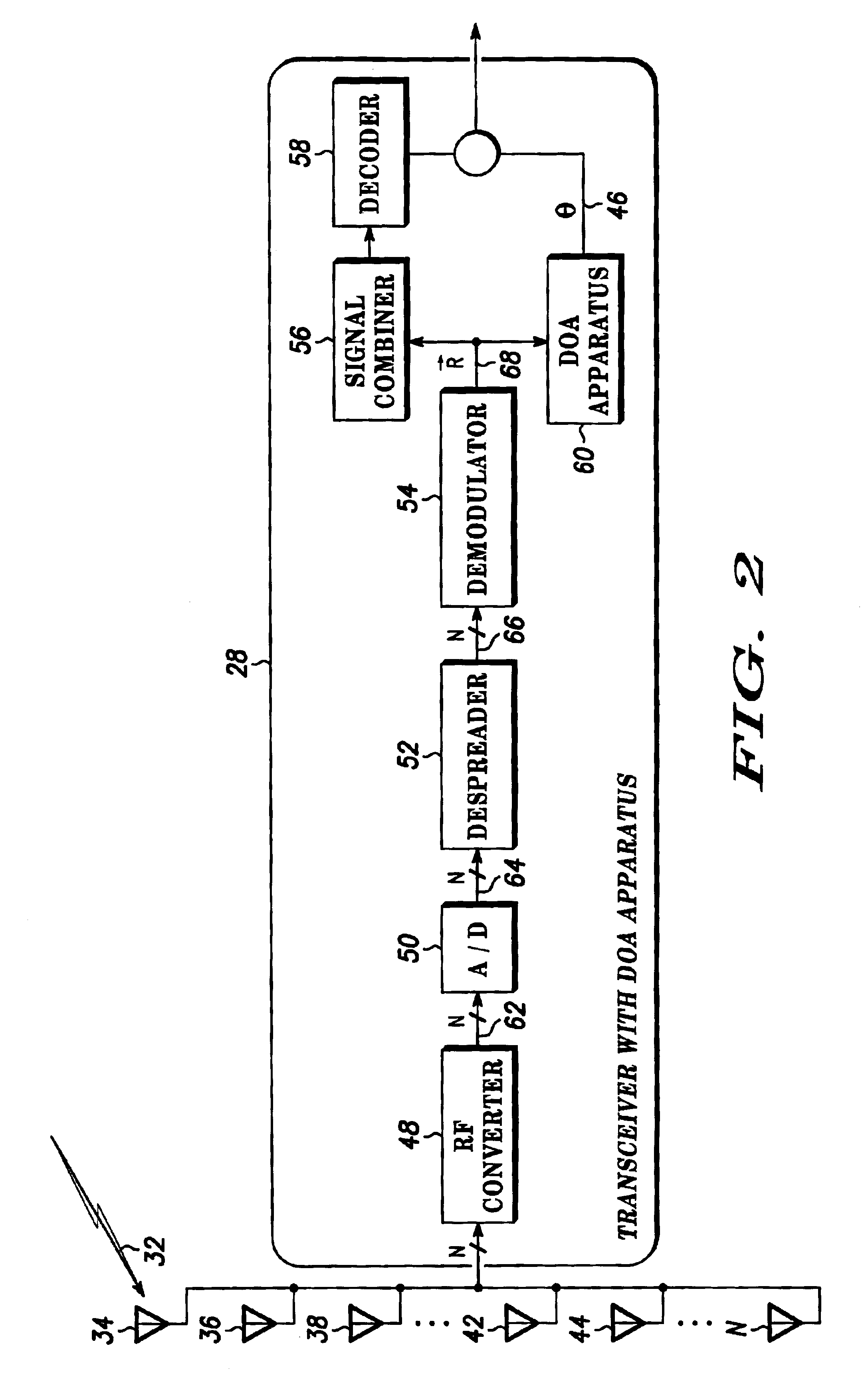
[0016]FIG. 1 is a block diagram of a wireless communication system 20 that includes an apparatus for determining the direction of arrival (DOA) of a remote unit (RU) 22 according to a preferred exemplary embodiment of the present invention. The wireless communication system 20 described in this detailed description of a preferred exemplary embodiment is directed to a cellular or personal communication system (PCS). However, the principles discussed herein can be readily applied to other wireless based, radio, cable television (CATV), telephony or satellite telecommunication systems as well as other data communications systems. Furthermore, while the wireless communication system 20 of the preferred exemplary embodiment of the present invention is configured to utilize a Code Division Multiple Access (...


PUM


Abstract

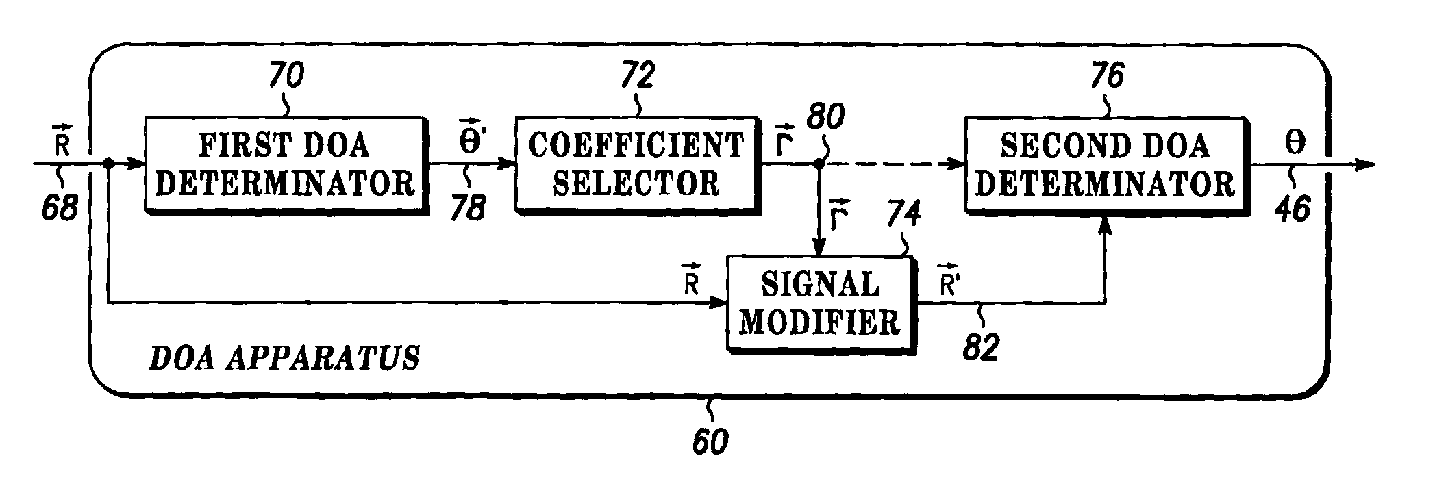
Methods and apparatus are provided for determining a direction of arrival (DOA) (46) of a Radio Frequency (RF) signal (32) transmitted by a remote unit (22) in a wireless communication system (20). The methods comprise receiving the RF signal (32) with multiple antennas (34,36,38,40,42,44) of the antenna array (26) and determining a preliminary direction of arrival (DOA) (78) for the RF signal (32) received with the multiple of antennas (34,36,38,40,42,44) of the antenna array (26). The methods also comprise selecting a coefficient (80) for the antenna array (26) based at least in part upon the preliminary DOA 978), modifying the RF signal (32) with the coefficient (80) to generate a modified RF signal (82), and determining the DOA (46) of the RF signal (32) with the modified RF signal (82).

Description

FIELD OF THE INVENTION[0001]The present invention generally relates to wireless communication systems, and more particularly to methods and apparatus for determining a direction of arrival (DOA) of a signal transmitted by a remote unit in a wireless communication system.BACKGROUND OF THE INVENTION[0002]There are numerous applications that can use the location of a remote unit in a wireless communication system. For example, the location of the remote unit can be used for emergency services, so that police, fire and / or medical services can be dispatched to the location of the subscriber requesting such an emergency service. In addition, the location of the remote unit can be used in detecting fraudulent use of the communication system, police investigations, and the like. Furthermore, the location of a remote unit can be used to improve performance of the wireless communication system. For example, wireless communication systems that utilize beam-forming transceivers can tune the bea...

Claims


Application Information

Patent Timeline
Patent Type & Authority Patents(United States)
IPC IPC(8): G01S3/02G01S3/74
CPCG01S3/023G01S3/74
Inventor ALEXANDER, JR., WILLIAM FRANCIS
Owner GOOGLE TECH HLDG LLC
Learn More