
Calibration method for use in head loading/unloading type disk apparatus

Inactive Publication Date: 2005-07-26
KK TOSHIBA
View PDF14 Cites 11 Cited by
  • Summary
  • Abstract
  • Description
  • Claims
  • Application Information

AI Technical Summary

Benefits of technology

[0007]Accordingly, it is an object of the present invention to provide a calibration method capable of accurately correcting the relationship between the value of a voice coil motor current flowing through a voice coil motor and a voice coil motor detection value detected by a voice coil motor velocity detection circuit, thereby performing accurate feedback control during loading / unloading.
[0008]It is another object of the present invention to provide a calibration method capable of improving the accuracy of a detected velocity by detecting a state in which the VCM resistance changes due to temperature change or the like and this may change the relationship between the VCM current value and the VCM velocity detection value, thereby performing more accurate velocity feedback control.

Problems solved by technology

This makes accurate velocity feedback control impossible to perform.

Method used


Image

  • Calibration method for use in head loading/unloading type disk apparatus
  • Calibration method for use in head loading/unloading type disk apparatus
  • Calibration method for use in head loading/unloading type disk apparatus

Examples


Embodiment Construction

[0045]An embodiment of the present invention will be described below with reference to the accompanying drawings.

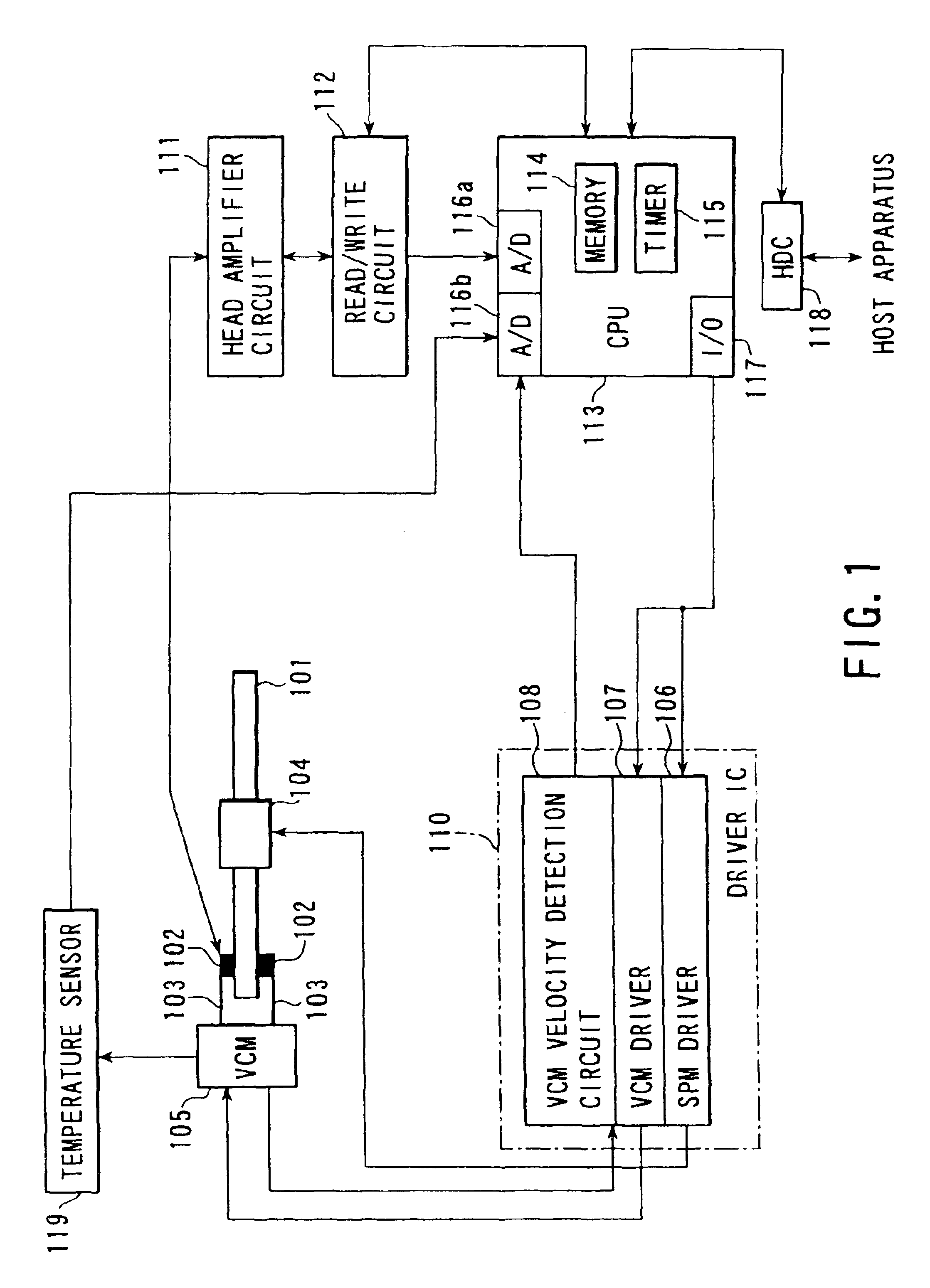
[0046]FIG. 1 is a block diagram showing the entire arrangement of a magnetic disk apparatus according to one embodiment of the present invention.

[0047]In FIG. 1, reference numeral 101 denotes a disk (magnetic disk) as a data recording medium; and 102, heads (magnetic heads) used to write (record) data to the disk 101 and read (reproduce) data from the disk 101. These heads 102 face the two surfaces of the disk 101. In the arrangement shown in FIG. 1, the magnetic disk apparatus has one disk 101. However, a plurality of disks can also be stacked in the magnetic disk apparatus.

[0048]A large number of concentric tracks are formed on each surface of the disk 101. A plurality of servo areas recording servo data for positioning control and the like are formed at equal intervals on each track. On the disk 101, these servo areas are radially arranged over the tracks from the cent...


PUM


Abstract

In a head loading / unloading type disk apparatus, accurate velocity feedback control is implemented by correcting any error in a VCM velocity detection value, which is caused by a temperature change or the like. At the start of loading control for loading a head from a ramp onto a disk, a carriage is pushed against an outer-periphery stopper to set the actual velocity of a VCM to zero. In this state, a VCM velocity detection value detected by a VCM velocity detection circuit is read out. On the basis of this velocity detection value, calibration for correcting the relationship between the VCM current value and the VCM velocity detection value is performed. In the period of head positioning control after the loading, an operation using a timer is periodically performed in which the carriage is pushed against an inner-periphery stopper, the calibration is reexecuted, and the head is returned to the original head position.

Description

CROSS-REFERENCE TO RELATED APPLICATION[0001]This application is a divisional application and claims the benefit of U.S. patent application Ser. No. 10 / 222,707 filed on Aug. 15, 2002 now U.S. Pat. No. 6,661,598, which is a divisional of U.S. patent application Ser. No. 09 / 382,444 filed on Aug. 25, 1999 which was issued on Dec. 15, 2002 as U.S. Pat. No. 6,496,319, and claims the benefit of the Japanese Patent Application No. 10-340058 filed on Nov. 30, 1998, the disclosure of each is incorporated herein by reference.BACKGROUND OF THE INVENTION[0002]The present invention relates to a calibration method for use in a head loading / unloading type disk apparatus and, more particularly, to a calibration method suited to automatic adjustment of the velocity detection value used in unloading.[0003]Recently, some disk apparatuses for recording and reproducing information by using a head, e.g., some small magnetic disk apparatuses use a head retraction method called a loading / unloading method. T...

Claims


Application Information

Patent Timeline
IPC IPC(8): G11B21/02G11B5/54G11B21/08G11B21/12
CPCG11B5/54G11B21/02G11B21/12G11B5/5534G11B5/5565
Inventor KUSUMOTO, TATSUHARUKAWACHI, HIDETOSHI
Owner KK TOSHIBA
Learn More