
Energetic material initiation device utilizing exploding foil initiated ignition system with secondary explosive material

a technology energy material, which is applied in the direction of electric fuzes, weapons, detonators, etc., can solve the problems of inconvenient use of pyrotechnic ignition system bulkhead, and inability to meet the requirements of pyrotechnic ignition system strength,

Inactive Publication Date: 2005-08-02
REYNOLDS SYST
View PDF10 Cites 50 Cited by
  • Summary
  • Abstract
  • Description
  • Claims
  • Application Information

AI Technical Summary

Problems solved by technology

Despite their success and relative safety in applications where detonation is desired, exploding foil initiators have not been widely used in pyrotechnic applications where deflagration rather than detonation is desired.
One drawback with the use of exploding foil initiators in pyrotechnic applications concerns the strength of the shockwave that is typically produced; the shockwave produced is ordinarily so strong as to actually damage or detonate the pyrotechnic material, rather than to initiate its burning as desired for proper operation.
The use of the bulkhead of the pyrotechnic ignition system, however, is undesirable because of the added weight and volume.
Conversely, if the shockwave is not sufficiently attenuated, there is a risk of damaging the pyrotechnic system and having a safety or reliability failure.
The variation in the output of the initiator and effects of temperature on the materials further compound this problem and require costly quality controls to ensure the safety and reliability of the system.
The close proximity of the bridge or hot wire to the pyrotechnic ignition material, however, increases the potential, relative to initiation systems that utilize exploding foil initiators, for inadvertent or accidental initiation as a result of EMI or lightning, for example.
These devices are inherently expensive, bulky and add significant weight.
Further the device must be located next to the pyrotechnic compound being ignited provide adequate safety, reducing the design options and increasing design complexity.

Method used


Image

  • Energetic material initiation device utilizing exploding foil initiated ignition system with secondary explosive material
  • Energetic material initiation device utilizing exploding foil initiated ignition system with secondary explosive material
  • Energetic material initiation device utilizing exploding foil initiated ignition system with secondary explosive material

Examples


Embodiment Construction

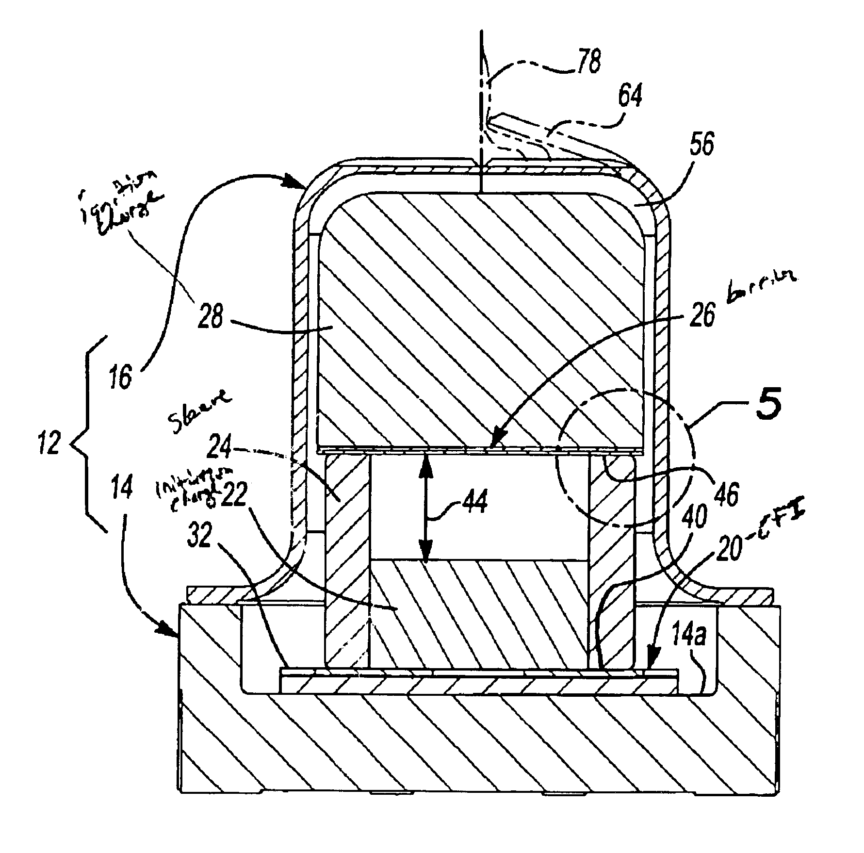
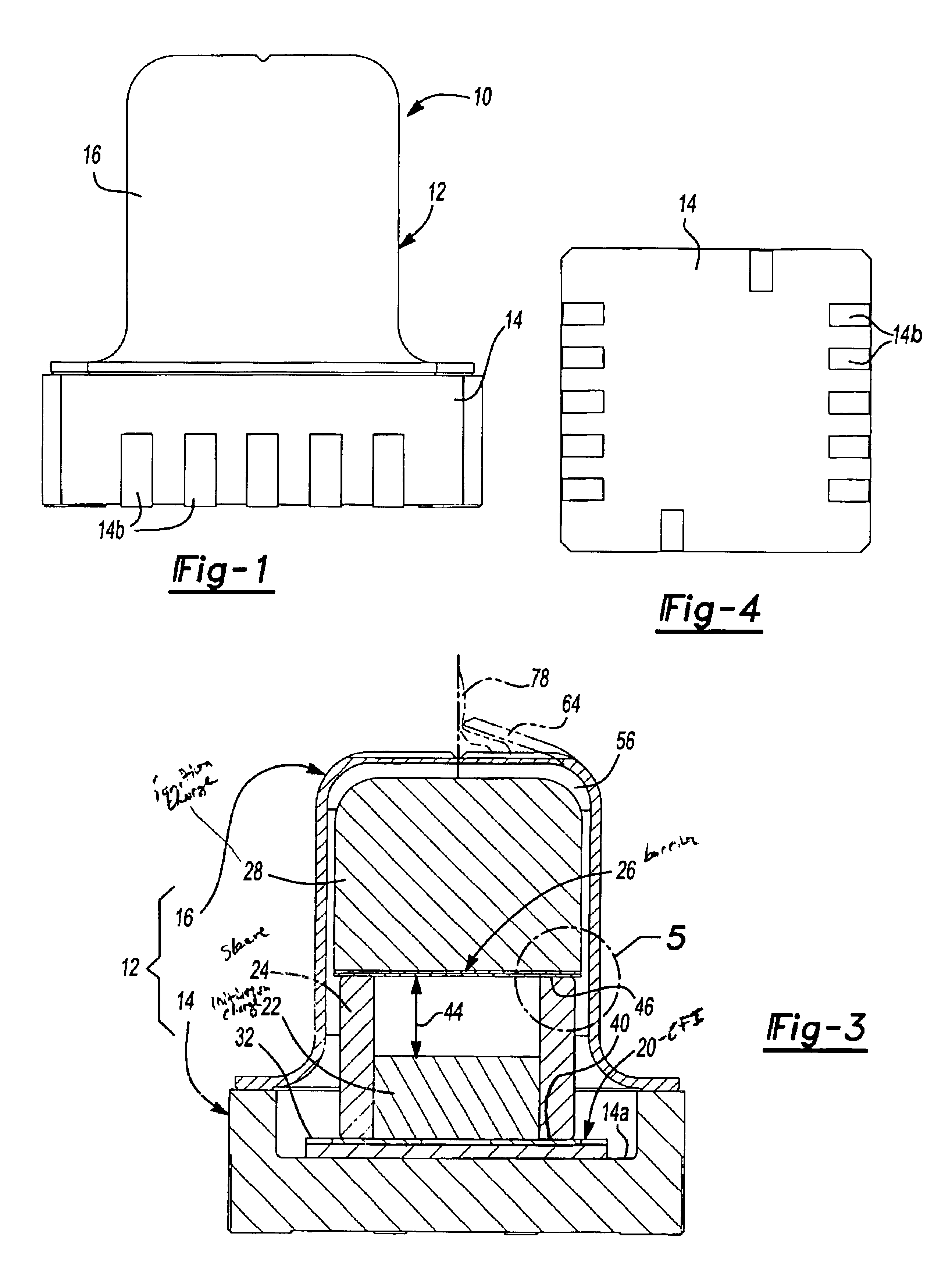
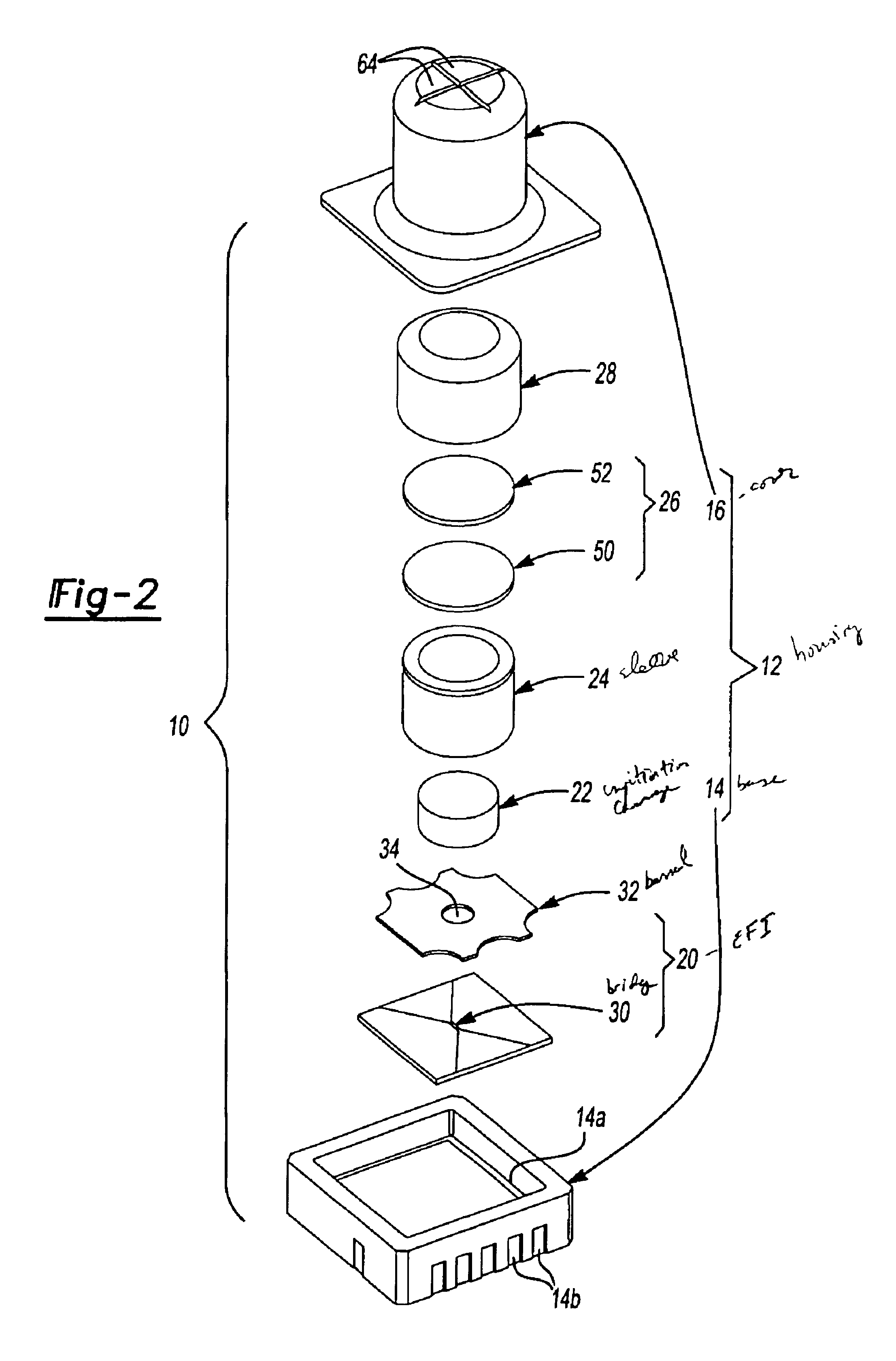
[0035]With reference to FIGS. 1 through 3 of the drawings, an energetic material initiation device constructed in accordance with the teachings of the present invention is generally indicated by reference numeral 10. The energetic material initiation device 10 is illustrated to include a housing 12, which in the particular example provided, includes a base 14 and a cover 16. As best seen in FIGS. 2 and 3, an exploding foil initiator 20, an initiation charge 22, a sleeve 24, a barrier structure 26 and an ignition charge 28 are disposed within the housing 12.

[0036]The exploding foil initiator 20 is conventional in its construction and operation and as such, will not be described in exhaustive detail herein. Briefly, the exploding foil initiator 20 includes a bridge 30, a flyer (not specifically shown) and a barrel 32. When the energetic material initiation device 10 is to be actuated, a high current pulse, typically in excess of 1000 amps, is passed through the bridge 30, causing the ...


PUM


Abstract

A device and method that employs a detonation event as an energy source for producing a pyrotechnic output. The device includes an initiation charge that is selectively detonated by an exploding foil initiator. Byproducts from the detonation event are attenuated by a barrier that is disposed between the initiation charge and an ignition charge. The barrier participates in a chemical reaction with the detonation byproducts to oxidize and burn. In this regard, the barrier serves as a fuel that is employed to ignite the ignition charge. The device includes a sealed housing in which the initiator, initiation charge and ignition charges are housed. The housing ruptures in response to the heat and pressure generated by the ignited ignition charge to release the pyrotechnic output.

Description

FIELD OF THE INVENTION[0001]The present invention generally relates to energetic material initiation devices and more particularly to an energetic material initiation device that converts a detonation shockwave to a deflagration output having a high pressure, high temperature impulse.BACKGROUND OF THE INVENTION[0002]Currently, exploding foil initiators (EFI's) represent the “state of the art” with regard to devices for initiating detonation in an explosive charge through a relatively high-energy pulse or shockwave as exploding foil initiators are insensitive to induced or radiated electrical energy, such as electromagnetic interference (EMI) or low energy pulses, and utilize a secondary explosive, which are relatively impervious to impacts and high temperatures, for producing the high-energy pulse. The ability to withstand impacts as well as electrical, electromagnetic and thermal energy renders exploding foil initiators relatively safe and thus very desirable for a significant numb...

Claims


Application Information

Patent Timeline
IPC IPC(8): F42B3/12F42B3/00
CPCF42B3/127
Inventor HENNINGS, GEORGE N.TESCHKE, DIETER K.REYNOLDS, RICHARD K.
Owner REYNOLDS SYST
Learn More