Stand for installing plurality of box bodies

a technology for installing a plurality of boxes, applied in the direction of casings/cabinets/drawers, instruments, casings/cabinets/drawers details of electrical appliances, etc., can solve the problems of increasing the space required for installation, increasing the thickness of the box body, and complicated configuration, so as to prevent the box body from falling down, reduce the entire width of the stand, and reduce the space needed for installing the plurality of box bodies

Inactive Publication Date: 2005-08-02
FUJITSU LTD
View PDF11 Cites 14 Cited by
  • Summary
  • Abstract
  • Description
  • Claims
  • Application Information

AI Technical Summary

Benefits of technology

[0011]It is a primary object of the present invention, which was devised to obviate the problems described above, to provide a stand for installing a plurality f box bodies, which is capable of reducing a space needed for installing a plurality of box bodies in parallel and preventing interference with radiation of the box body.
[0013]Thus, according to the present invention, the plurality of box bodies are integrally held, and hence the entire width of the stand has at least a dimension obtained by adding width of all the box bodies. Therefore, the entire width of the stand can be decreased by reducing the interval between the box bodies to the greatest possible degree.
[0015]Herein, an interval of a portion, for holding the box body, of the middle stand may be set to an interval larger than a gap needed for heat radiation, at which the box bodies adjacent to each other are installed. In this case, it is feasible to prevent the box bodies from interfering with heat radiation each other.
[0016]As explained above, according to the present invention, the plurality of box bodies are integrally held, and hence the entire width becomes comparatively large for a height of the box body. It is therefore possible to prevent the box body from falling down even when reducing the interval between the box bodies.
[0017]Accordingly, the entire width of the stand can be decreased by reducing the interval between the box bodies to the greatest possible degree, whereby a space needed for installing the plurality of box bodies can be reduced and can be thus saved.
[0018]Moreover, since the interval of the portion, for holding the box body, of the middle stand is set equal to or larger than a gap necessary for heat radiation of the box bodies adjacent to each other, it is feasible to prevent the box bodies from interfering the heat radiation each other.

Problems solved by technology

Further, the box body has been increasingly thinned and downsized over the recent years.
The conventional stand 1 described above has, however, a problem in which a space necessary for installation increases when installing the plurality of box bodies 11, 11 in parallel.
A further problem is that this stand 2 is structured to rotatably fit the arms 21, 21 to the box body 11, and therefore its configuration becomes complicated.

Method used


Image

  • Stand for installing plurality of box bodies
  • Stand for installing plurality of box bodies
  • Stand for installing plurality of box bodies

Examples


Embodiment Construction

[0030]Embodiments of the present invention will hereinafter be described with reference to the accompanying drawings in FIGS. 1 through 7.

[0031]In the embodiment, the present invention is applied to a stand for a family network server (a home server) defined as a peripheral device to a computer.

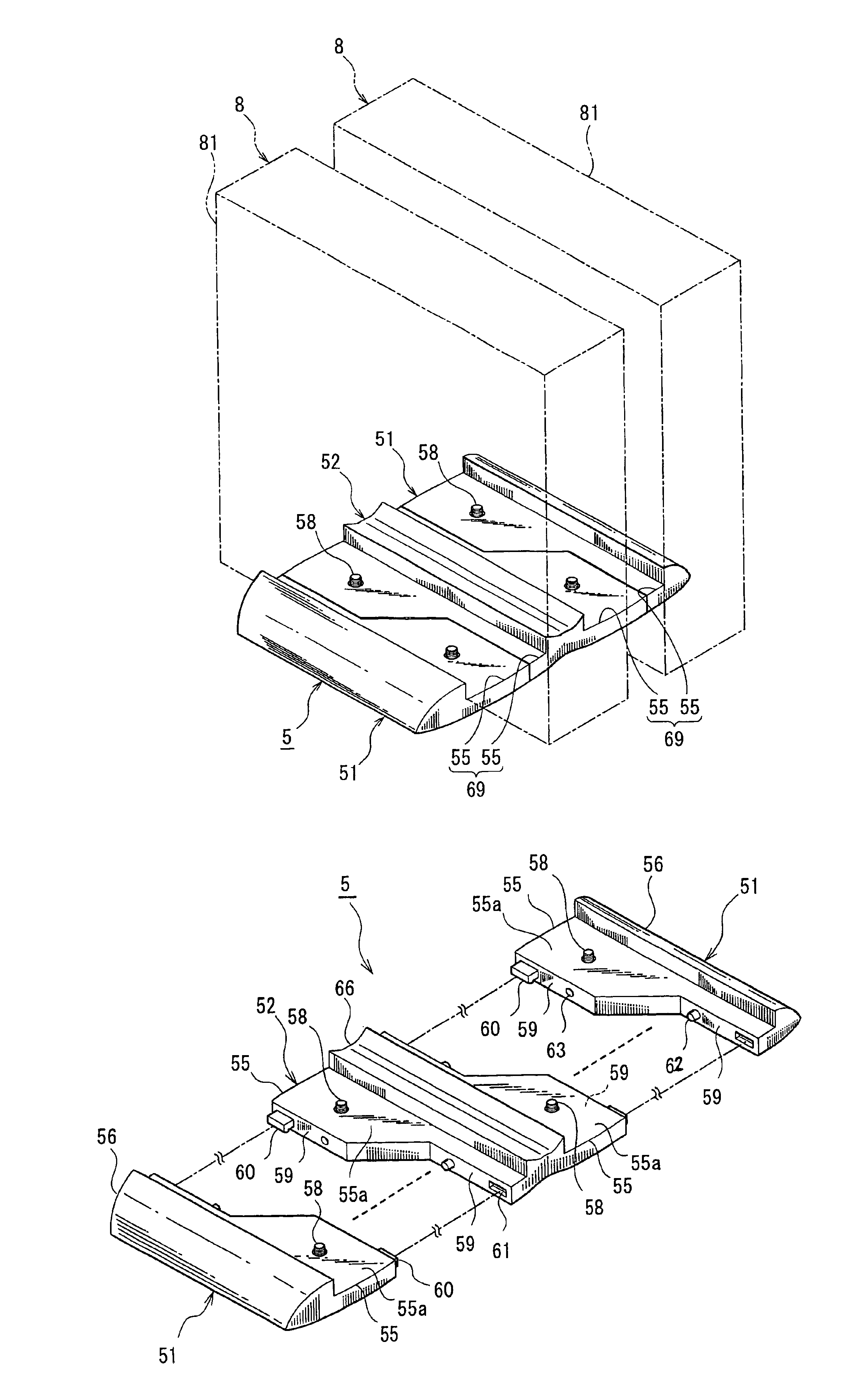
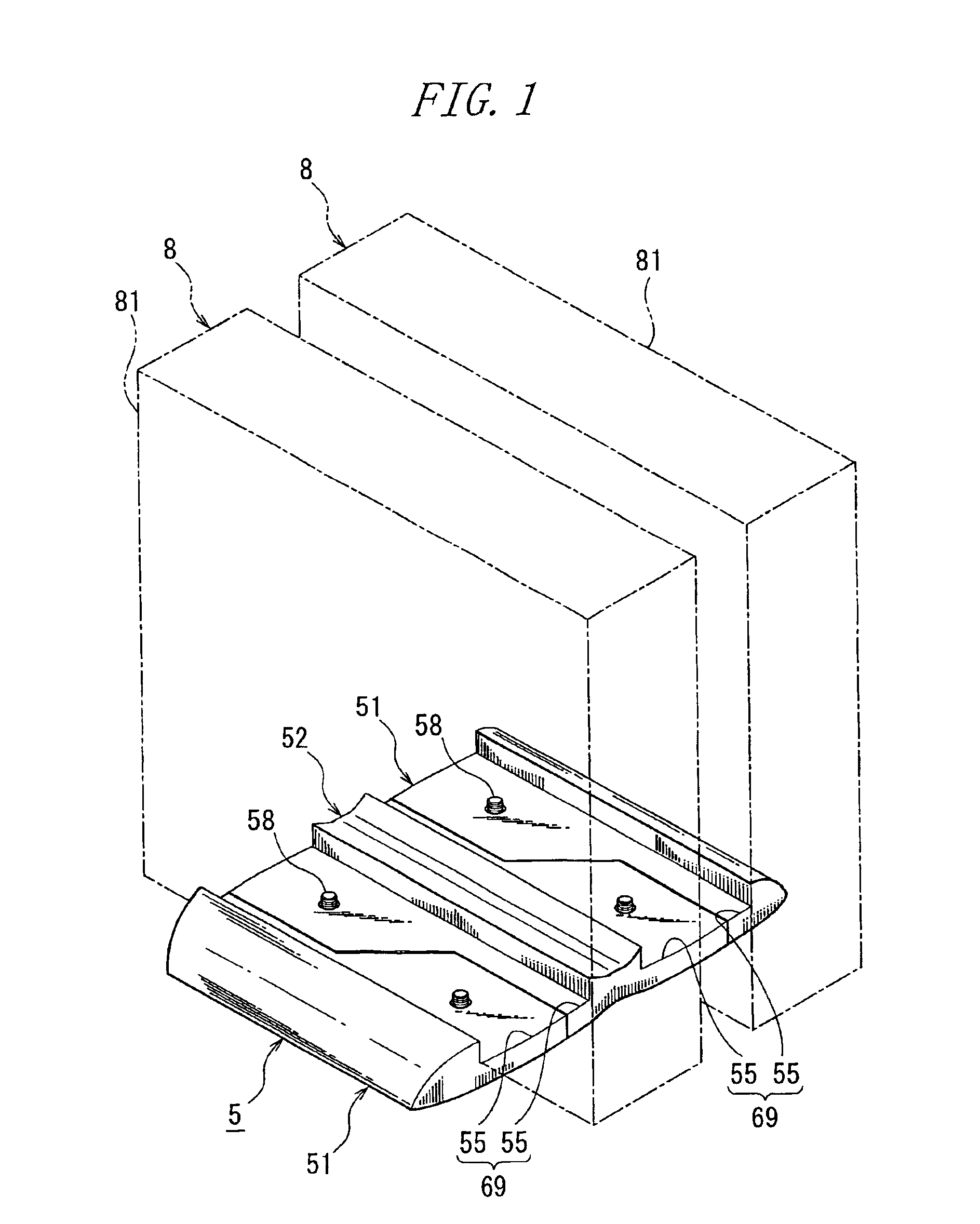
[0032]FIG. 1 illustrates a stand 5 to which the present invention is applied. This stand 5 is structured with a plurality of family network servers 8 installed in parallel and in a state of vertically placed thereon. A box body 81 of each of the family network servers 8 is configured thin substantially in a rectangular parallelopiped shape.

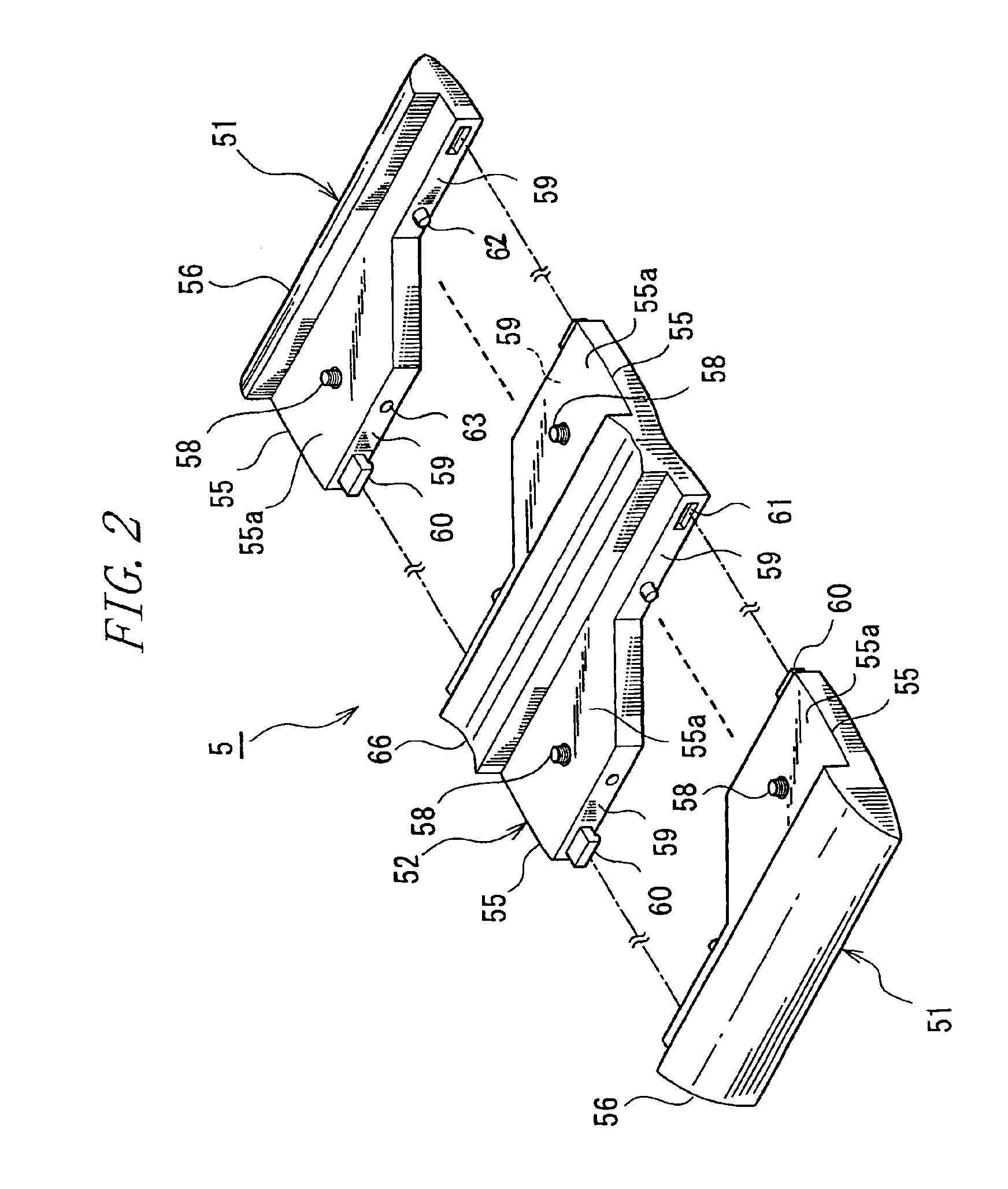
[0033]The stand 5 includes a pair of outer stands 51, 51 for supporting the outer surfaces of the box bodies 81, 81 disposed on the outsides among the plurality of box bodies 81, . . . installed in parallel, a middle stand 52, interposed between the pair of outer stands 51, 51, for supporting the face-to-face surfaces of the box bodies 81, 81 adjacent to ea...


PUM


Abstract

A stand for installing a plurality of box bodies is capable of reducing a space needed for installing the plurality of box bodies in parallel and preventing interference with heat radiation of each box body. A stand 5 for installing a plurality of each box bodies 81 in parallel includes a pair of outer stands 51, 51 holding the box bodies 81 disposed on the outer sides from the sides of outer surfaces of the box bodies 81, a middle stand 52 disposed between these outer stands 51, 51 and holding both of the box bodies 81, 81 adjacent to each other from the face-to-face sides thereof, and a connection mechanism detachably connecting the stands 51 52.

Description

BACKGROUND OF THE INVENTION[0001]The present invention relates generally to a stand for installing a plurality of box bodies and more particularly to a stand suitable when using peripheral devices to a computer in a way that places them vertically.[0002]A box body of each of the peripheral devices to the computer is, in the great majority of cases, formed substantially in a rectangular parallelopiped shape. Further, the box body has been increasingly thinned and downsized over the recent years. In the case of vertically installing such a thin type box body, it is required that a fall-down thereof be prevented. It is therefore general to secure the stand to the bottom of the box body.[0003]FIG. 8 shows a conventional stand 1. This stand 1 includes a recessed portion 12 for accommodating the bottom of a box body 11 in a peripheral device 10 to the computer, and legs 13, 13 protruding sideways from both sides of this recessed portion 12 and each taking substantially a triangular shape ...

Claims


Application Information

Patent Timeline
Patent Type & Authority Patents(United States)
IPC IPC(8): F16M11/00G06F1/18G06F1/16H05K5/02
CPCF16M11/00F16M11/22G06F1/16G06F1/181H05K5/0204F16M2200/02F16M2200/08
Inventor SHIDA, ARATAAOKI, ISAO
Owner FUJITSU LTD
Why Eureka
Try Eureka