
A shielding structure and terminal

A technology of shielding structure and shielding cover, applied in the field of communication, can solve problems such as radiation interference, avoid poor consistency, avoid unreliable grounding, and reduce labor costs

Active Publication Date: 2021-01-08
VIVO MOBILE COMM CO LTD
View PDF8 Cites 0 Cited by
  • Summary
  • Abstract
  • Description
  • Claims
  • Application Information

AI Technical Summary

Problems solved by technology

[0003] Embodiments of the present invention provide a shielding structure and a terminal to solve the problem of radiation interference between different electronic device modules during the operation of the terminal

Method used


Image

  • A shielding structure and terminal
  • A shielding structure and terminal
  • A shielding structure and terminal

Examples


Embodiment Construction

[0028] In order to make the technical problems, technical solutions and advantages to be solved by the present invention clearer, the following will describe in detail with reference to the drawings and specific embodiments.

[0029] Generally, in order to solve the interference problem of the camera module to the antenna module, the whole camera module can be wrapped with conductive cloth or copper foil, and the conductive cloth or copper foil can be grounded. For example: wrap the bottom and side of the camera with conductive cloth or copper foil, and then use the conductive cloth to ground the exposed copper area at the bottom of the camera module or the metal middle frame. This method mainly has the following three defects:

[0030] 1. Adding auxiliary materials such as conductive cloth or copper foil around the camera will increase the cost of materials. In addition, it will also increase a lot of labor costs;

[0031] 2. In order to ensure the grounding reliability of c...


PUM


Abstract

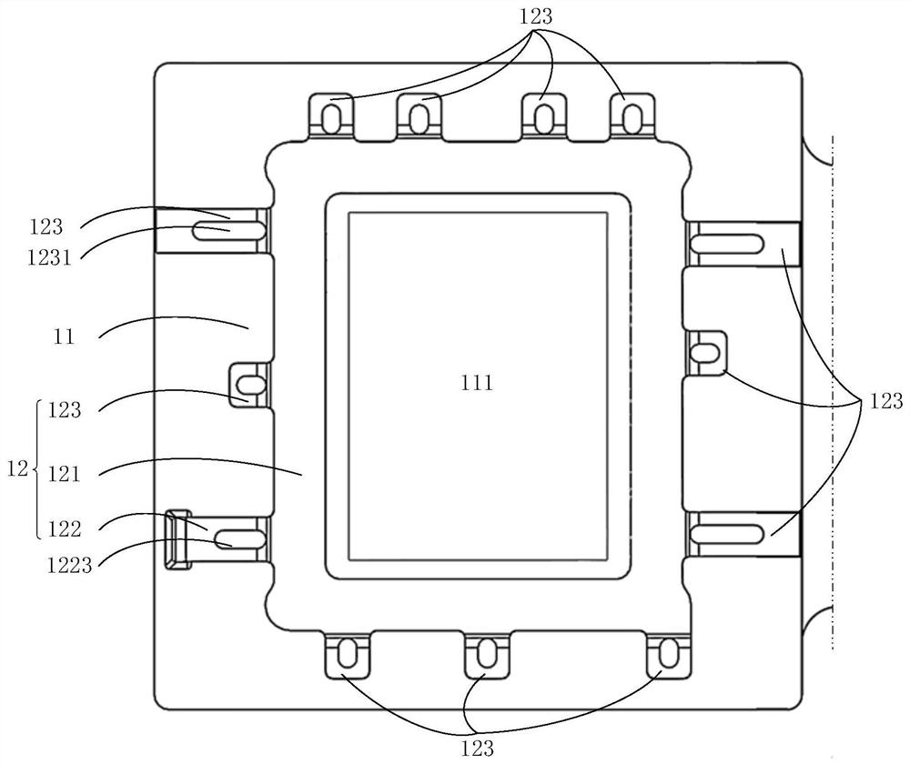
An embodiment of the present invention provides a shielding structure and a terminal. The shielding structure includes: an interference source, the interference source includes: an electron radiation area; a shielding cover, the shielding cover is fixedly connected to the interference source; the shielding cover covers the interference source Above at least part of the electron radiation area, the ground terminal of the shielding cover is electrically connected to the ground terminal of the interference source. Through the shielding structure of the embodiment of the present invention, it can shield and absorb the radiation interference generated by itself, or prevent other modules from generating radiation interference to itself, and can solve the interference problem between different electronic device modules.

Description

technical field [0001] The invention relates to the field of communication technology, in particular to a shielding structure and a terminal. Background technique [0002] During the operation of the terminal, one electronic device module will inevitably cause radiation interference to another electronic device module during the working process, and this phenomenon seriously affects the quality of the terminal. Taking the camera module and antenna module as an example, the physical locations of the camera module and antenna module cannot be completely avoided, and the photoelectric conversion chip will generate high-frequency radiation during the working process of the camera module. The frequency signal is very sensitive, and the camera module will inevitably interfere with the antenna module. For example, when making a video call through the camera module, due to the interference of the camera module to the antenna module, the incoming call cannot be received. Seriously a...

Claims


Application Information

Patent Timeline
Patent Type & Authority Patents(China)
IPC IPC(8): H05K9/00H04N5/225
CPCH05K9/002H05K9/0058H04N23/50H04N23/57
Inventor 聂磊
Owner VIVO MOBILE COMM CO LTD
Learn More