Subcovered printing mode for a printhead with multiple sized ejectors

a printing mode and printhead technology, applied in printing and other directions, can solve the problems of reducing the print speed of the printer and the limited amount of information that can be transferred to the print medium

Inactive Publication Date: 2005-08-02
FUNAI ELECTRIC CO LTD
View PDF25 Cites 5 Cited by
  • Summary
  • Abstract
  • Description
  • Claims
  • Application Information

AI Technical Summary

Benefits of technology

[0016]An advantage of the present invention is that the large nozzles can fill in dark colors with fewer passes of the printhead, and the small nozzles can be used where less grain is needed.
[0017]Another advantage of the present invention is that more information is transferred to the print medium without requiring additional passes of the printhead.

Problems solved by technology

A problem is that multiple passes of the printhead over the same raster line decreases the print speed of the printer.
Another problem is that the amount of information that can be transferred to the print medium is limited by the fact that only one size of ink drop can be deposited on the print medium.

Method used


Image

  • Subcovered printing mode for a printhead with multiple sized ejectors
  • Subcovered printing mode for a printhead with multiple sized ejectors
  • Subcovered printing mode for a printhead with multiple sized ejectors

Examples


first embodiment

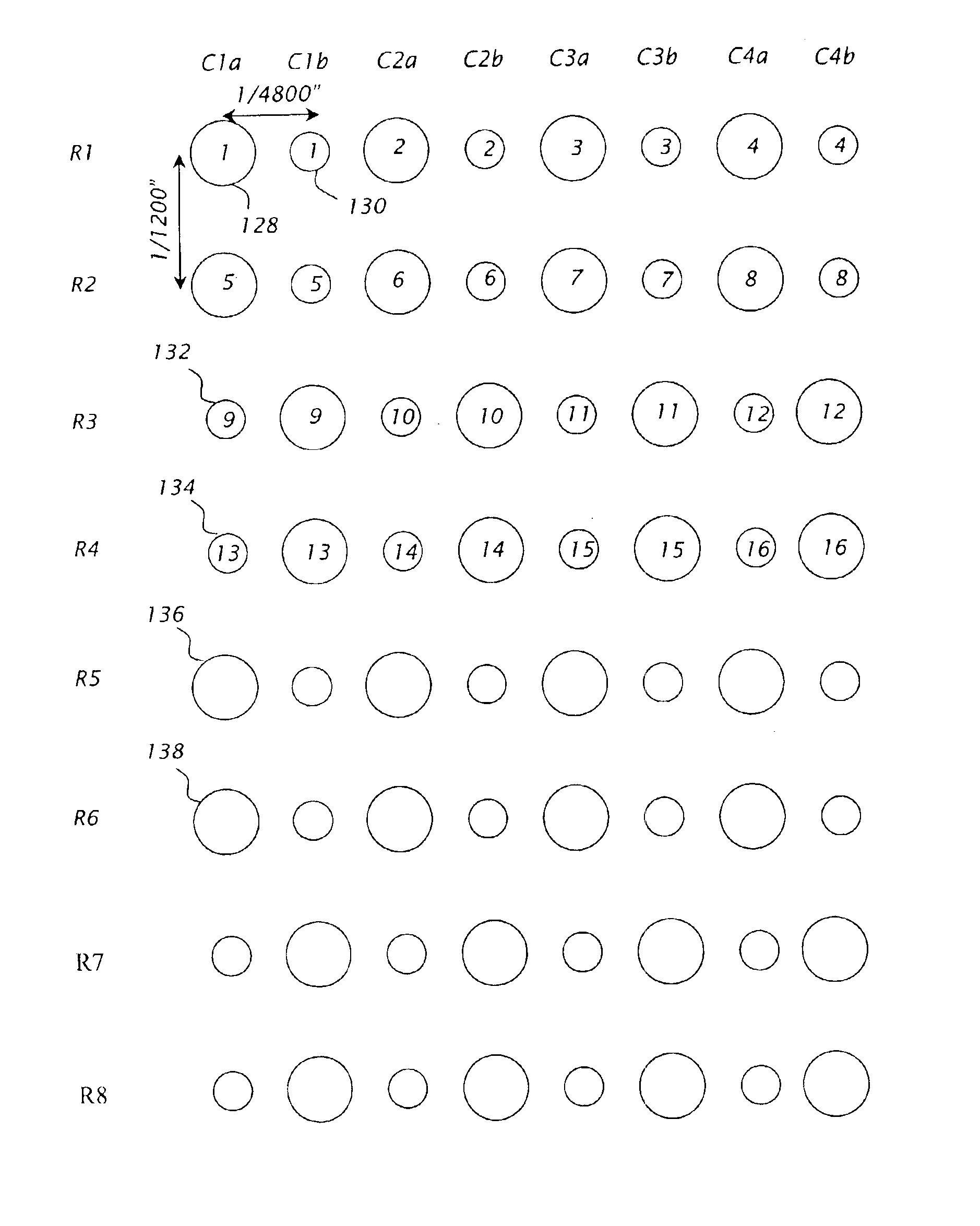
[0058]It may also be desirable to achieve an odd multiple of the reported resolution of 1200 dpi, such as 3600×1200 dpi printed output. described above, this would imply processing the data as a “perfectly covered” 1800×1200 dpi print mode, then expanding as described to obtain the 3600×1200 dpi printed output. However, traditional halftoning algorithms are not designed to process the data as 1800×1200 dpi, when reporting 1200 dpi to the application, as effectively and as efficiently as an integer or a power-of-two multiple.

[0059]The second embodiment described below not only provides a printing method (see FIGS. 10 and 11) using a conventional halftoning algorithm in conjunction with a sub-covered print mode, but also provides a method for achieving varying print resolutions using a conventional halftoning algorithm. This second embodiment provides a method of printing with a two-nozzle-size printhead in a “sub covered” print mode whereby halftone generates a pattern at, for examp...

third embodiment

[0063]the present invention is shown in FIG. 12. The discussion above with regard to FIG. 11 applies equally as well to FIG. 12.

[0064]Compared to the 4800 dpi case described in the first embodiment, the second and third embodiments provide for a 3600 dpi print mode that utilizes the same data from the halftoning algorithm as the 4800 dpi case. This is accomplished by combining portions of each of the eight columns of FIG. 9 in the 4800 dpi mode to fit into the six columns of the 3600 dpi mode. The resultant 3600 dpi mode provides a print quality advantage over a true sub-covered 3600 dpi mode, while providing a speed advantage over a perfectly covered 3600 dpi print mode.

[0065]Another advantage of the present invention is that it can be easily extended to different printers to provide them with varying print resolutions. For instance the present invention is easily extended to 3000 or 4200 dpi resolution.

[0066]The present invention has been described as being implemented using color...


PUM


Abstract

A method of printing with an ink jet printer includes providing a printhead having a plurality of first nozzles with a first size and a plurality of second nozzles with a second size larger than the first size. The first nozzles and the second nozzles are alternatingly disposed in a vertical direction. Print data corresponding to first columns of pixel locations is provided. The print data includes for each pixel location in the first columns both a respective large dot print datum and a respective small dot print datum. One of the respective large dot print datum and the respective small dot print datum is printed at a first pixel location of the corresponding pixel locations in the first columns. Second columns of pixel locations interleaved with the first columns of pixel locations are provided. The other of the respective large dot print datum and the respective small dot print datum not printed in said first pixel location of the first columns is printed at a first pixel location of the second columns of pixel locations.

Description

[0001]This a Divisional of application Ser. No. 10 / 074,923, filed Feb. 11, 2002, now U.S. Pat. No. 6,592,203.BACKGROUND OF THE INVENTION[0002]1. Field of the Invention[0003]The present invention relates to an ink jet printer, and, more particularly, to a method of printing with high resolution using an ink jet printer.[0004]2. Description of the Related Art[0005]An ink jet printhead includes a plurality of nozzles arranged vertically, i.e., in the paper feed direction, with respect to a printed page. The nozzles have a fixed vertical spacing between them, such as 1 / 600 inch for a 600 dots per inch (dpi) printhead. Additionally, the array of nozzles travels horizontally repeatedly across the page, with some amount of advance of the paper in the vertical direction between such scans, dropping dots at a fixed horizontal distance, which can also be 1 / 600 inch. The term “horizontal”, as used herein, indicates the direction of printhead scan, perpendicular to the vertical, paper feed dire...

Claims


Application Information

Patent Timeline
Patent Type & Authority Patents(United States)
IPC IPC(8): B41J2/15B41J2/21B41J2/145
CPCB41J2/15B41J2/2125
Inventor BATES, JOHN BOOTHHEYDINGER, SCOTT MICHAELMAYO, RANDALL DAVIDMARRA, III, MICHAEL ANTHONYREEL, RICHARD LEE
Owner FUNAI ELECTRIC CO LTD
Why Eureka
Try Eureka