Apparatus for ligating living tissues

a technology of living tissue and ligating apparatus, which is applied in the field of living tissue ligating apparatus, can solve the problems of high emergency, complicated and time-consuming work, and high difficulty in reducing patient pain, so as to reduce the time of surgical operation, reduce pain, and facilitate the effect of operation

Inactive Publication Date: 2005-08-02
OLYMPUS CORP
View PDF6 Cites 280 Cited by
  • Summary
  • Abstract
  • Description
  • Claims
  • Application Information

AI Technical Summary

Benefits of technology

[0016]With the above construction, a plurality of clips mounted in the introducing tube can be retained in a body cavity merely by inserting the clipping apparatus in the body cavity one time. This makes it unnecessary to do a work that the clipping apparatus is retracted to the outside of the body cavity every time one clip is retained in the body cavity, and clips are mounted again and inserted into the body cavity again. In this manner, a surgical operation time can be reduced, and thus, a patient's pain can be reduced. In addition, the manipulating wire is inserted into a tube channel other than that in which clips are arranged. Thus, the clips can be retained in the body cavity one by one speedily, easily, and reliably without interference between the clips each and manipulating wire.

Problems solved by technology

Therefore, there has been a disadvantage that complicated and very time consuming work is required.
In addition, there are many disease cases requiring high emergency when a clip is applied to a bleeding site.
In such disease cases, such a complicated and time consuming work has been very problematic.
However, there has been a problem that providing the heating element at the distal end portion of the sheath complicates an equipment structure, and requires another heating source.
However, this temperature control has been very difficult.
Therefore, there has been a problem that a complicated and time consuming work is required during clipping ligation.

Method used


Image

  • Apparatus for ligating living tissues
  • Apparatus for ligating living tissues
  • Apparatus for ligating living tissues

Examples


first embodiment

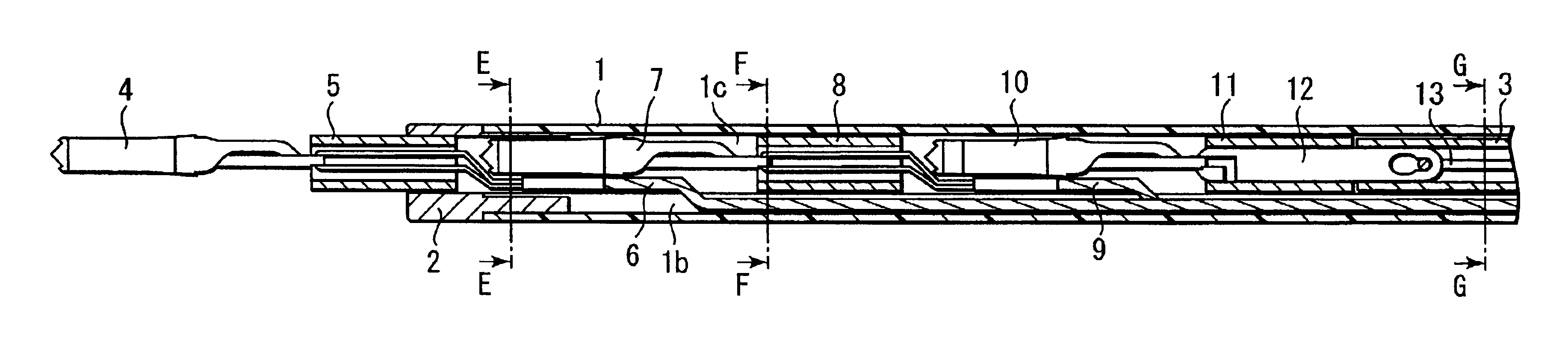
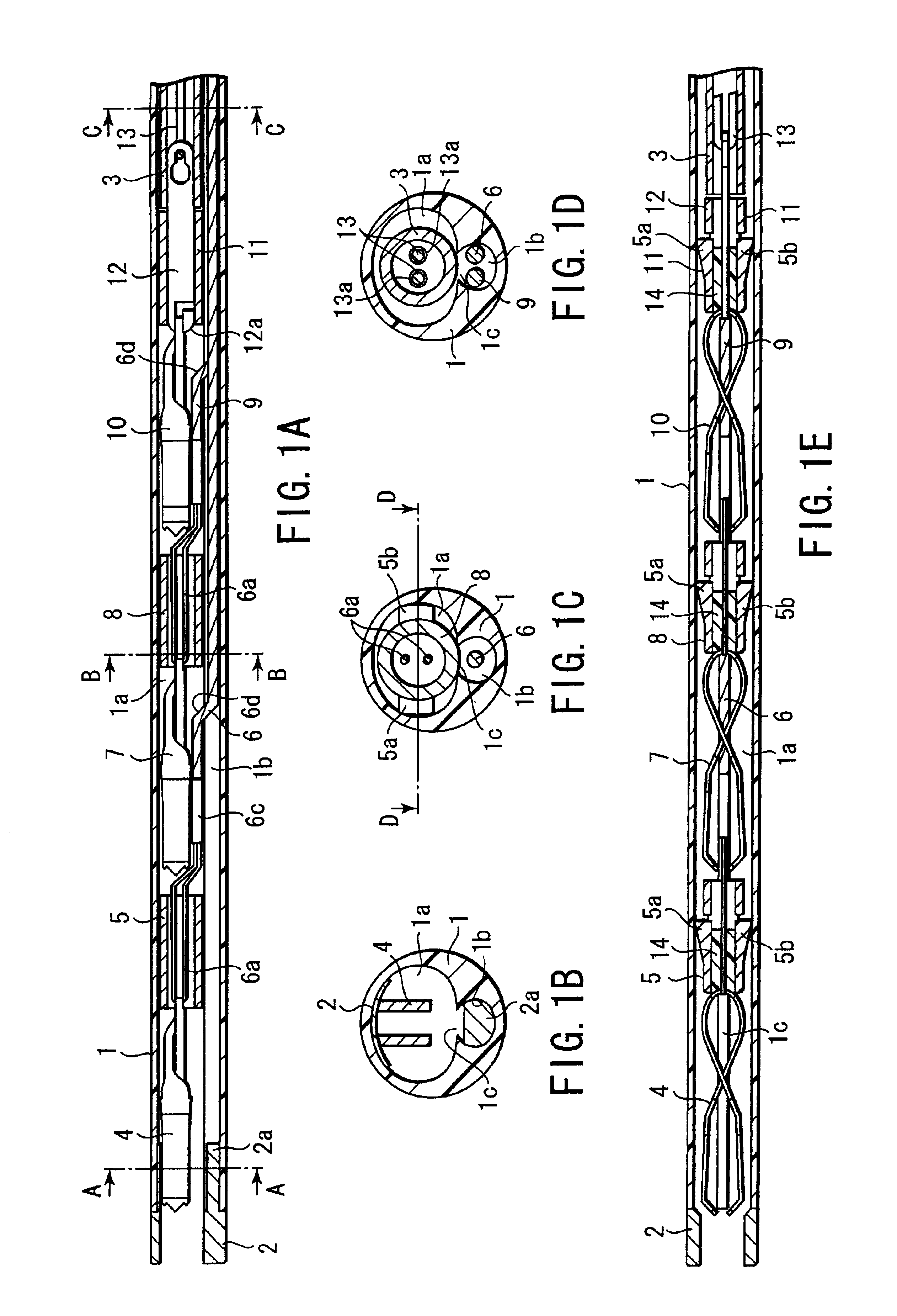
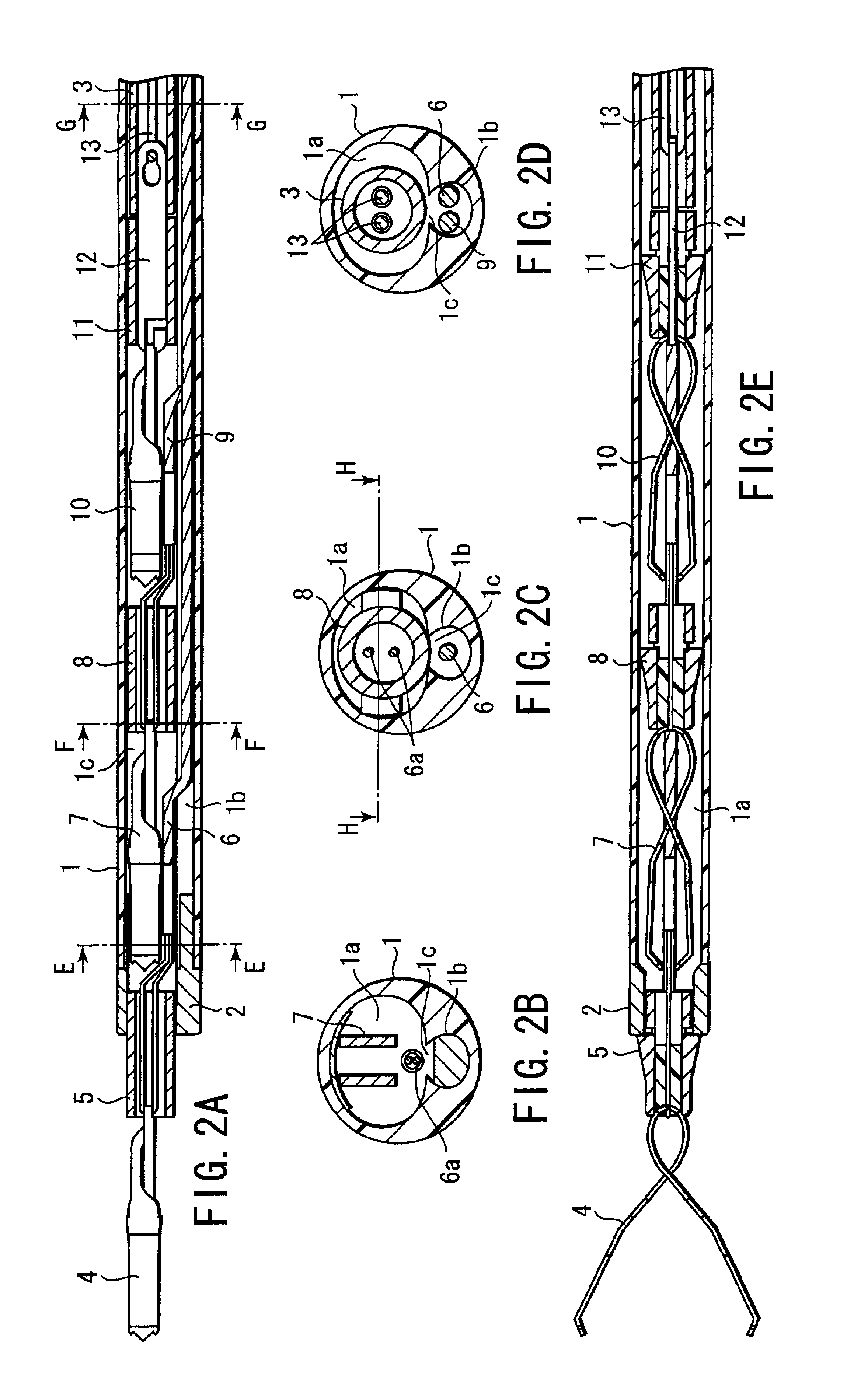
[0086]FIG. 1A to FIG. 11 show the present invention. As shown in FIG. 1A and FIG. 1E, an introducing tube 1 has flexibility such that the tube can be inserted into an endoscope channel. A distal end tip 2 is provided at a distal end portion of this introducing tube 1. The introducing tube 1 is provided as a tune sheath that consists of a polymeric resin described later, for example, and a first tube channel 1a and a second tube channel 1b are provided in parallel to each other over an axial direction.

[0087]As shown in FIG. 1B to FIG. 1D, the first tube channel 1a is formed in a substantially oval shape on its transverse cross section, and has a large inner diameter so that a clip and a clip tightening ring described later can be inserted. The second tube channel 1b is also formed in a substantially oval shape on its transverse cross section, and has a small inner diameter so that a manipulating wire described later can be inserted. The first tube channel 1a and second tube channel 1...

third embodiment

[0133]Now, working of a third embodiment will be described here.

[0134]The introducing tube 30 of the ligating apparatus is introduced into a body cavity via the endoscope channel inserted into the body cavity. Then, a distal end portion of the introducing tube 30 is located in close proximity of a clipping target tissue, for example, a gastric mucous membrane tissue. When a retracting side 34b of the manipulating wire 34 inserted into the second tube channel 30b is retracted to the frontal side of the introducing tube 30, the manipulating wire 34 is returned to form a loop section at a portion of the holding element 33. Then, an advancing side 34a of the manipulating wire 34 advances to the distal end side of the introducing tube 30. Therefore, as shown in FIG. 14A to FIG. 14E, the most frontal clip 4 and clip tightening ring 5 are protruded from the distal end portion of the distal end tip 31.

[0135]When the clip tightening ring 5 is located in the distal end tip 31, the ring drops ...

fourth embodiment

[0151]Now, working of a fourth embodiment will be described here.

[0152]The introducing tube 50 of the ligating apparatus is introduced into a body cavity via the channel of the endoscope inserted into the body cavity. Then, a distal end portion of the introducing tube 50 is located in close proximity to a clipping target tissue, for example, a gastric mucous membrane tissue. When the retracting side 54b of the manipulating wire 54 inserted into the second tube channel 50b is retracted to the frontal side, the manipulating wire 54 is returned to from a loop section at the arc shaped portion 51c of the holding element 51. Then, the advancing side 54a of the manipulating wire 54 advances to the distal end side of the introducing tube 50. Therefore, as shown in FIG. 19, the clip 4 and clip tightening ring 5 at the most frontal portion of the introducing tube 50 are protruded diagonally upwardly from the opening portion 50d.

[0153]As shown in FIG. 20, when the clip tightening ring 5 is l...


PUM


Abstract

An apparatus for ligating living tissues comprises an introducing tube capable of being inserted into a living body cavity, a manipulating wire movably inserted into the introducing tube, and clips for ligating living tissues, the clips being arranged in the introducing tube. The introducing tube has a plurality of tube channels. A plurality of clips are arranged in series in the tube channel, and a manipulating wire engaged with the clips is arranged at the other tube channel.

Description

CROSS-REFERENCE TO RELATED APPLICATIONS[0001]This application is based upon and claims the benefit of priority from the prior Japanese Patent Application No. 2001-088382, filed Mar. 26, 2001, the entire contents of which are incorporated herein by reference.BACKGROUND OF THE INVENTION[0002]1. Field of the Invention[0003]The present invention relates to a living tissue ligating apparatus for ligating living tissues by inserting the apparatus into a living body cavity in a transendoscopic manner.[0004]2. Description of the Related Art[0005]Conventionally, it has been well known that apparatuses for clipping living tissues are disclosed in Jpn. UM. Appln. KOKAI Publication No. 2-6011 and Jpn. Pat. Appln. KOKAI Publication No. 63-267345. In Jpn. UM. Appln. KOKAI Publication No. 2-6011, a clip and a manipulating wire is engaged with each other via a hook provided at a distal end portion of the manipulating wire and a connecting member provided at a distal end of the hook, the connecting ...

Claims


Application Information

Patent Timeline
Patent Type & Authority Patents(United States)
IPC IPC(8): A61B17/122A61B17/12A61B17/128A61B17/064A61B17/28
CPCA61B17/1227A61B17/1285A61B17/0643A61B17/122
Inventor MURAMATSU, JUNICHIKOBAYASHI, TSUKASA
Owner OLYMPUS CORP
Why Eureka
Try Eureka