Rechargeable lithium battery

a rechargeable lithium battery and lithium battery technology, applied in the direction of cell components, flat cell grouping, sustainable manufacturing/processing, etc., can solve the problems of inability to work a terminal cap and an insulating mold, increase the production cost of a prismatic rechargeable battery, and inability to meet the requirements of the market, etc., to prolong the charging and discharging cycle, prolong the cycle life, and prolong the cycle li

Inactive Publication Date: 2005-08-02
CANON KK
View PDF9 Cites 71 Cited by
  • Summary
  • Abstract
  • Description
  • Claims
  • Application Information

AI Technical Summary

Benefits of technology

[0029]Another object of the present invention is to provide a thin type rechargeable lithium battery in which the anode and the cathode are not internally shorted even when charging and discharging are alternately repeated over a long period of time and which excels in durability.
[0030]A further object of the present invention is to provide a thin type rechargeable lithium battery having a prolonged cycle life (a prolonged charging and discharging cycle life).

Problems solved by technology

However, this method results in a remarkable increase in the production cost of a prismatic rechargeable battery and therefore, it is not acceptable in practice.
When the capping is of a thin thickness of, for instance, less than about 5 mm, it is extremely difficult to work a terminal cap and an insulating mold at the capping and it is also extremely difficult to work a liquid introduction port at the capping.
The welding in this case exerts a thermal adverse effect to the insulating mold situated in the vicinity of the position where the welding is conducted.
However, this sheet type rechargeable battery has disadvantages such that because the laminate film is insufficient in terms of the physical strength, the battery is liable to deform or it is liable to be damaged, and therefore, there is a limit for a range where the battery can be used.
However, the aluminum foil 1007 is of a thin thickness (about 10 μm), and therefore, there is a tendency in that moisture invasion into the battery main body 1003 cannot be perfectly prevented by the aluminum foil 1007.
In this case, it is difficult to sufficiently seal neighborhood regions of the two power output terminals 1001.
This situation is liable to entail a problem such that the reliability of the battery is deteriorated.
This situation entails a decrease in the capacity density of the battery.
However, to bend the peripheral portion involved deteriorates the reliability of the laminate film 1005, where a fear of permitting moisture to be invaded into the battery main body is likely to increase.
However, the rechargeable battery having such configuration as shown in FIG. 11 described in document 1 has disadvantages such that because the cover plate 1104 comprises a simple sheet-like plate whose thickness is thin, the cover plate 1104 is insufficient in terms of the physical strength, and because of this, when a stress is vertically or diagonally applied to the battery vessel 1105, the battery vessel is liable to deform, where there is a fear that the cathode and the anode suffer internal shorts.

Method used


Image

  • Rechargeable lithium battery
  • Rechargeable lithium battery
  • Rechargeable lithium battery

Examples


example 1

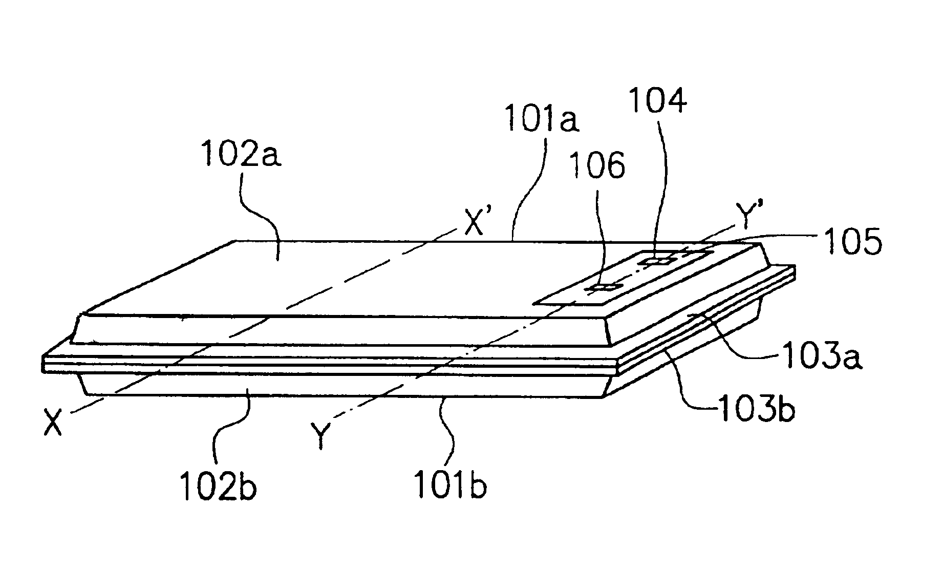
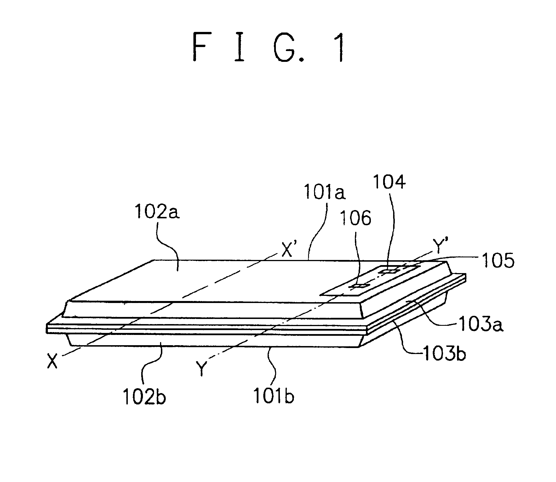
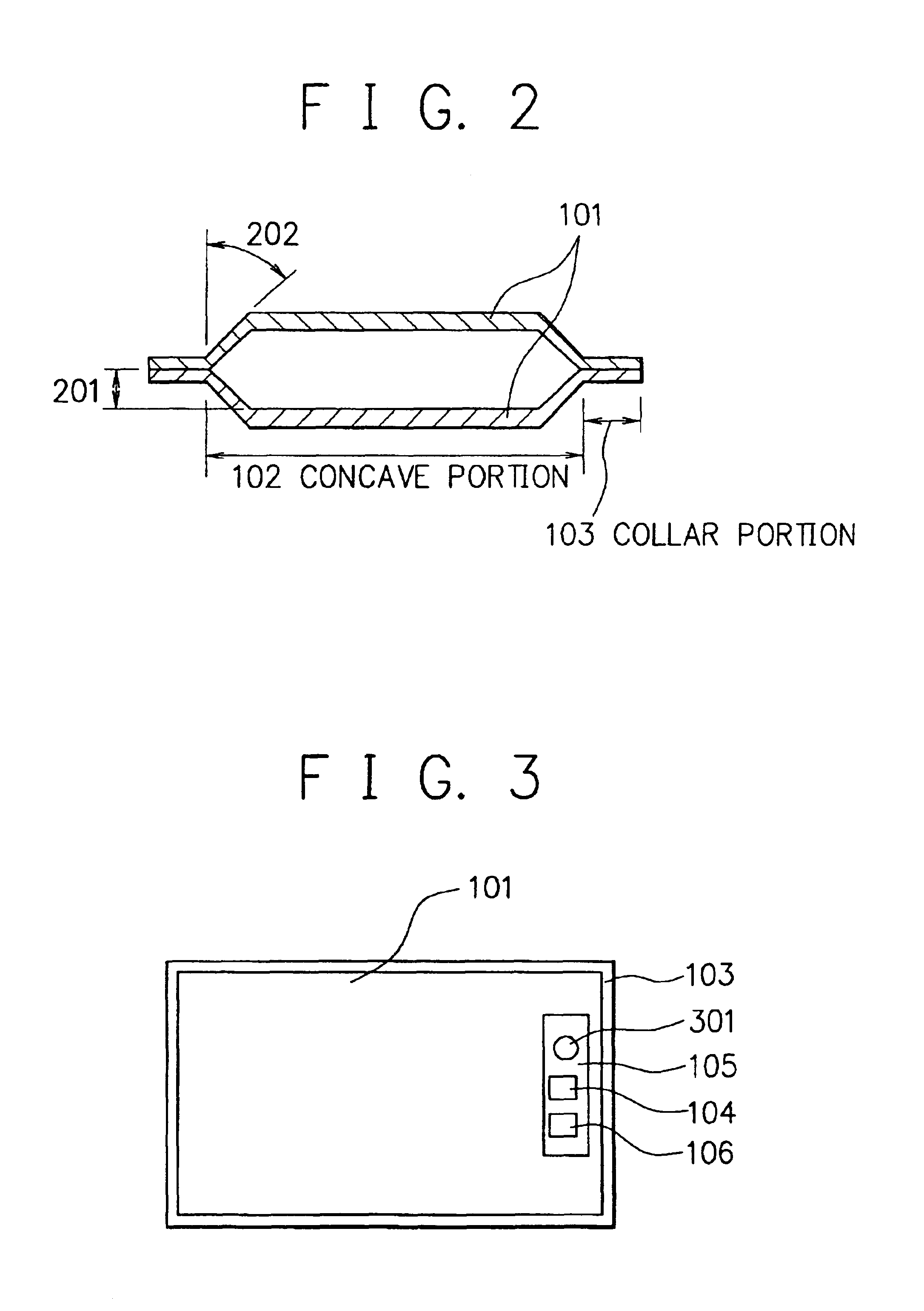
[0115]In this example, there was prepared a thin type rechargeable lithium battery having such configuration as shown in FIGS. 1 to 4 in the following manner.

1. Preparation of Cathode:

[0116]90 parts by weight of LiCoO2 as a cathode active material, 5 parts by weight of natural graphite as an electrically conductive auxiliary, and 5 parts by weight of polyvinylidene fluoride as a binder were mixed to obtain a mixture. The mixture was mixed with 50 parts by weight of N-methyl-2-pyrrolidone as a solvent to obtain a paste having a viscosity of 3000 cps. The past was applied onto opposite sides of an aluminum foil having a thickness of 20 μm as a collector, followed by subjecting to drying thereby to form a coat layer on each of the opposite sides of the aluminum foil.

[0117]The resultant obtained in the above was subjected to pressing to obtain an element having a thickness of 200 μm which comprises the aluminum foil sandwiched between the two layers each as a cathode active material lay...

example 2

[0130]The procedures of Example 1 were repeated, except that the preparation of the anode in the step 2 in Example 1 was conducted as will be described below, to obtain five thin type rechargeable lithium batteries.

Preparation of Anode:

[0131]60 parts by weight of a powdery tin material having an average particle size of 3 μm as an anode active material and 5 parts by weight of carboxymethyl cellulose as a binder were mixed to obtain a mixture. The mixture was mixed with 35 parts by weight of deionized water as a solvent to obtain a paste having a viscosity of 2000 cps. The past was applied onto opposite sides of a copper foil having a thickness of 12 μm as a collector, followed by subjecting to drying thereby to form a coat layer on each of the opposite sides of the aluminum foil. The resultant obtained was subjected to pressing to obtain an element having a thickness of 180 μm which comprises the copper foil sandwiched between the two layers each as an anode active material layer. ...

example 3

[0132]The procedures of Example 1 were repeated, except that without using the separators and the electrolyte solution, a solidified electrolyte material layer was formed on the surface of each cathode and also on the surface of each anode as will be described below, to obtain five thin type rechargeable lithium batteries.

[0133]On the opposite surfaces of each of six cathodes having a size of 52 mm×70 mm prepared in the same manner as in the step 1 in Example 1 and also on the opposite surfaces of each of seven anodes having a size of 52 mm×70 mm prepared in the same manner as in the step 2 in Example 1, a coating liquid obtained by mixing 70 parts by weight of methoxypolyethylene glycol monoacrylate and 30 parts by weight of polyethylene glycol dimetacrylate to obtain a mixture and mixing said mixture with 400 parts by weight of an electrolyte solution obtained by dissolving 1 M (mol / liter) of lithium hexafluorophosphate dissolved in 1 liter of a mixed solvent obtained by mixing et...


PUM

PropertyMeasurementUnit
widthaaaaaaaaaa
thicknessaaaaaaaaaa
thicknessaaaaaaaaaa

Abstract

A thin rechargeable lithium battery having a battery main body enclosed between sealing members (a) and (b), at least sealing member (a) having a concave portion that extends to either side from a central position so as to have a peripheral collar portion (a-i) which surrounds the concave portion, sealing member (b) having a peripheral collar portion (b-i) corresponding to the collar portion (a-i) of sealing member (a) and the two sealing members (a) and (b) being opposingly arranged such that the face of said concave portion of sealing member (a) faces sealing member (b) through the battery main body, wherein collar portions (a-i) and (b-i) are mutually welded, and either sealing member (a) or (b) is provided with a power output terminal having electrical continuity with the battery main body and an insulating portion for insulating said terminal.

Description

BACKGROUND OF THE INVENTION[0001]1. Field of the Invention[0002]The present invention relates to a rechargeable lithium battery preferably shaped in a thin form and a process for producing said rechargeable lithium battery.[0003]2. Related Background Art[0004]In recent years, the global warming of the earth because of the so-called greenhouse effect due to an increase in the content of CO2 gas in the air has been predicted. For instance, in thermal electric power plants, thermal energy obtained by burning a fossil fuel is being converted into electric energy, and along with burning of such fossil fuel, a large amount of CO2 gas is being exhausted in the air. Accordingly, in order to suppress this situation, there is a tendency of prohibiting to newly establish a thermal electric power plant. Under these circumstances, so-called load leveling practice has been proposed in order to effectively utilize electric powers generated by power generators in thermal electric power plants or th...

Claims


Application Information

Patent Timeline
Patent Type & Authority Patents(United States)
IPC IPC(8): H01M2/22H01M2/02H01M10/04H01M2/12H01M10/36H01M10/40H01M6/40H01M10/05H01M10/052H01M10/0525H01M50/103H01M50/119H01M50/133H01M50/528H01M50/55H01M50/555
CPCH01M2/0207H01M2/0215H01M2/0277H01M2/06H01M2/08H01M2/12H01M2/22H01M10/0436H01M10/052H01M10/0525H01M2/021Y10T29/49108H01M6/40H01M10/05Y02E60/122Y02T10/7011Y10T29/49107Y10T29/4911Y10T29/49114Y02E60/10H01M50/555H01M50/30H01M50/528Y02P70/50H01M50/133H01M50/103H01M50/55H01M50/119H01M10/058Y02T10/70
Inventor KAWAKAMI, SOICHIROOGURA, TAKAO
Owner CANON KK
Why Eureka
Try Eureka