Apparatus for viewing a display of a portable communication device

a portable communication device and display device technology, applied in the direction of mountings, telephone set constructions, instruments, etc., can solve the problems of inconvenient or impractical wireline connection formation, difficult viewing of display indicia displayed upon the user display, and inconvenient use of wireline connection extending to the mobile communication station. , to achieve the effect of facilitating viewing of display displayed on the user display by users

Inactive Publication Date: 2005-08-02
NOKIA CORP
View PDF2 Cites 61 Cited by
  • Summary
  • Abstract
  • Description
  • Claims
  • Application Information

AI Technical Summary

Benefits of technology

[0017]Because the optical lens is of dimensions that permit the viewing of display indicia upon the user display while also permitting unimpeded access by the user to the actuation keys of the device, the user is readily able concurrently to view the display indicia in magnified form and to actuate the actuation keys.
[0019]In one aspect of the present invention, the optical lens exhibits a magnification factor that increases the apparent image size of display indicia displayed on the user display. The magnification of the size of the display indicia is determined by the characteristics of the optical lens. The magnification factor is, e.g., of a magnification level that doubles (2×) or triples (3×) the display indicia. By increasing the apparent size of the display indicia, the user's perception of the indicia is improved. And, at such magnification levels, substantially the entire screen of the user display is viewable, in magnifiable form, by the user of the communication device. Display indicia displayed upon a user display measuring only several centimeters in length and several centimeters in width are magnified so that the display indicia displayed thereon during effectuation of a communication service appears to be larger than the small heights and widths that are permitted of display upon the display screen of the user display.
[0024]In these and other aspects, therefore, apparatus, and an associated method, is provided for a portable radio communication station. The portable radio communication station has a user display that selectably displays display indicia of an initial display size. The user display is positioned at a face surface of the radio communication station. Viewing by a user of a display displayed on the user display is facilitated. An optical lens is selectably positionable above the user display of the radio communication station. The optical lens is of a dimension at least to cover at least a portion of the user display when positioned thereabove. The optical lens exhibits a magnification level that magnifies the display indicia of the initial display size to be of a magnified display size when viewed by the user through the optical lens. A mounting arm is engageable with both the optical lens and the radio communication station. The mounting arm mounts the optical lens in position above the user display.

Problems solved by technology

Because wireline, i.e., fixed, connections are not required to interconnect the communication stations between which data is to be communicated, communications are effectuable through use of a radio communication system between communication stations positioned at locations at which the formation of wireline connections would be inconvenient or impractical.
For instance, when one, or more, of the communication stations is permitted mobility, use of wireline connections extending to the mobile communication station is oftentimes impractical.
Display indicia displayed upon the user display is more difficult to view when the user display is of such small dimensions.
When a user of a mobile station is near-sighted or far-sighted, the display indicia is even more difficult to view.

Method used


Image

  • Apparatus for viewing a display of a portable communication device
  • Apparatus for viewing a display of a portable communication device
  • Apparatus for viewing a display of a portable communication device

Examples


Embodiment Construction

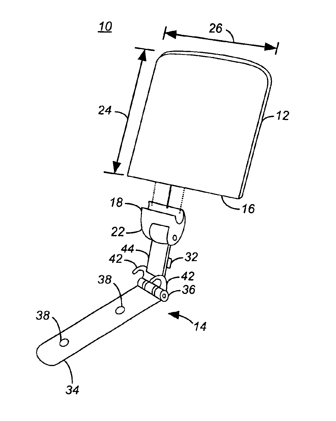
[0032]Referring first to FIG. 1, the apparatus, shown generally at 10, of an embodiment of the present invention includes an optical lens 12 and a mounting arm 14. The lens 12 and mounting arm 14 are releasably engageable with one another. Here, while the lens and mounting arm are shown in exploded view, the elements are connected theretogether during their operation to facilitate a viewing of display indicia displayed upon a user display of a portable communication device.

[0033]The separate elements of the apparatus are connected together by positioning a bottom 16 of the optical lens to abut with a clamp brace 18 of a clamp member 22. The clamp member 22 is positioned at an end of the mounting arm and forms a portion of the mounting arm. The clamp brace 18 is of a configuration permitting the reception of the end 16 of the optical lens thereat and to clampingly engage the optical lens when received thereat. In one implementation, the clamp member is formed of a substantially rigid...


PUM


Abstract

Apparatus, and an associated method, for facilitating viewing of a display indicia displayed upon a user display of a portable communication device, such as a cellular mobile station. An optical lens that exhibits a selected magnification level is positioned to overlay the user display. A mounting arm engages with the optical lens and with the portable communication device to affix the optical lens so that when the user of the communication device views the user display, the display indicia displayed thereon is magnified by the optical lens.

Description

[0001]The present invention relates generally to a manner by which to facilitate viewing of display indicia upon a user display of a portable communication device, such as a portable radio communication station. More particularly, the present invention relates to apparatus, and an associated method, by which to magnify the display indicia displayed upon the user display. A user of the portable communication device is able better to perceive the display indicia.[0002]An optical lens is selectably positioned to overlay the user display. The optical lens is affixed in position by a mounting arm that connects the optical lens with the portable communication device. The optical lens is of dimensions to permit the user to view the display indicia through the optical lens, but also not to hinder the user's ability to actuate actuation keys that also form part of the personal communication device. User interactive communication services and applications, such as interactive gaming applicati...

Claims


Application Information

Patent Timeline
Patent Type & Authority Patents(United States)
IPC IPC(8): G02B27/02H04M1/21
CPCG02B27/027H04M1/21
Inventor GVENTER, BRIANMORR, ANDREAS
Owner NOKIA CORP
Why Eureka
Try Eureka