
Easy-locking buckle structure

a buckle and buckle technology, applied in the direction of buckles, snap fasteners, mechanical devices, etc., can solve the problems of inconvenient use for female users, inability to operate the buckle elements, and especially to position, and eventually tear

Inactive Publication Date: 2005-08-09
YANG SHIH SHENG
View PDF6 Cites 13 Cited by
  • Summary
  • Abstract
  • Description
  • Claims
  • Application Information

AI Technical Summary

Benefits of technology

"The invention is a buckle structure that is easy to lock and unlock. It is designed to make it simple for users to attach and detach articles with the buckle. The structure also provides a better elastic-locking effect, which extends the life of the buckle. The buckle is made up of a male buckle element and a female buckle element, which are connected together through a post and a socket with a cylinder. The female buckle element has slots and connecting pins at the bottom for connecting with the socket. The buckle can be locked and detached repeatedly, making it convenient for users. The slightly upward holding tab of the male buckle element makes it easy for users to operate the buckle structure. Overall, the invention provides a simple yet effective buckle structure that improves the user experience."

Problems solved by technology

1. The user must press the buckle sets with force so that they can lock together. This may be quite inconvenient for a female user.
2. In connection with the combination of the male and female buckle sets, as the female buckle is designed to have substantially the same bore diameter as the outer diameter of the male buckle, it is not easy for the user to operate the buckle elements, and particularly to position them.
3. When separating the buckle elements, in the absence of the holding tab, the user must pull and drag the woven fabric layer therebetween, which will always eventually tear, given the firm combination of the male and female buckle elements.

Method used


Image

  • Easy-locking buckle structure
  • Easy-locking buckle structure
  • Easy-locking buckle structure

Examples


Embodiment Construction

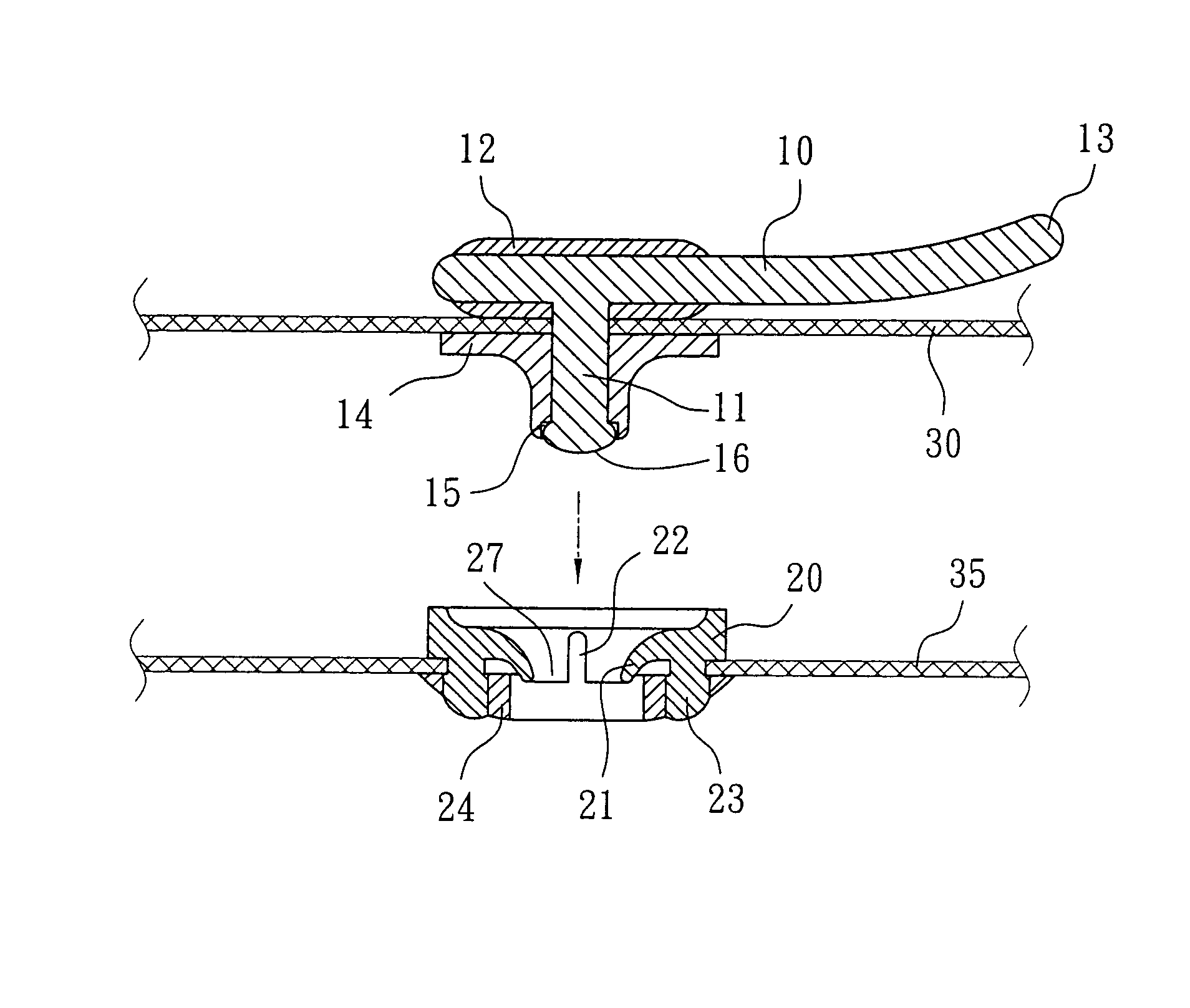
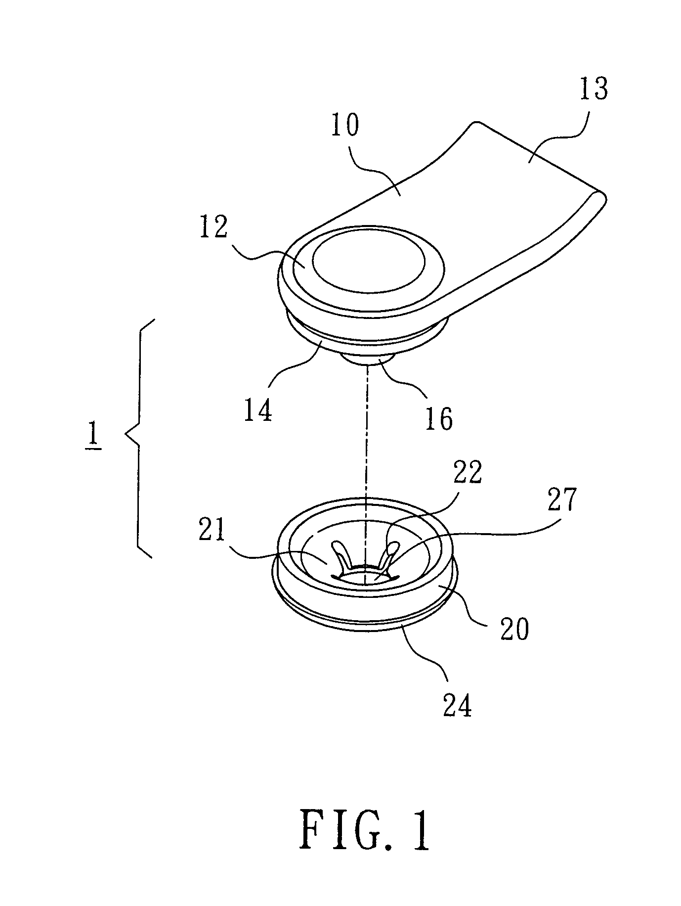
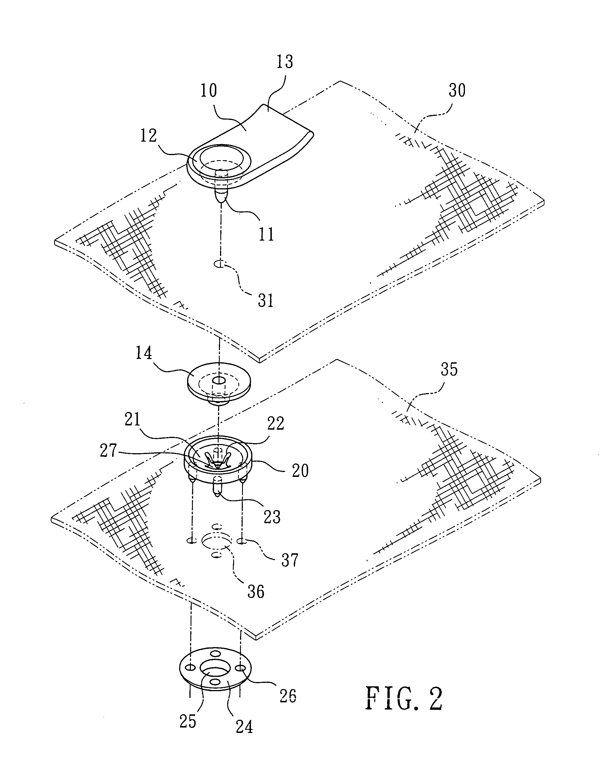
[0022]Referring to FIGS. 1 and 2, the buckle structure 1 according to the invention is composed of a male buckle element 10 in the form of a rectangular tab and a female buckle element 20 having a smaller area than that of the male buckle element. The fore end of the rectangular tab is formed around a round press button, below the center of which a post 11 extends downwardly. The top of the press button may combine with a cover 12, while the top of the post 11 may engage with a socket 14 in the form of a cylinder with a hole. The post 11 may be pressed with the socket to become a blunt end 16. The inner edge of the top of the cylinder with a hole can be provided with a depressed step edge 15 (as shown in FIG. 3). The other end of the tab raising upwardly to form a holding tab 13.

[0023]The female buckle element 20 is combined with the male buckle element 10 by means of the socket 14. A conical recess 21 with a hole 27 is provided in the center of the female buckle element 20, while t...


PUM


Abstract

An easy-locking buckle structure is composed of a male buckle element and a female buckle element having a smaller area than that of the male buckle element. A post extends downwardly from the bottom of one end of the male buckle element for engagement with a socket with a cylinder, while an upwardly raising holding tab is provided at the other end of the male buckle element. A conical recess with a through hole is provided in the center of the female buckle element. Said conical recess is provided with slots at its sides for connecting with a socket. Holes are pre-punched on the articles to be applied with the buckle such that the post of the male buckle element can pass through and engage with the socket, while the connecting pins of the female buckle element pass through the punched holes on the article such that the conical recess with the hole can aim at and pass through the punched hole on the article before the socket under the article is locked with the female buckle element.

Description

BACKGROUND OF THE INVENTION[0001](a) Technical Field of the Invention[0002]The present invention relates to an easy-locking buckle structure, particularly to a buckle structure enabling a user to lock and detach the male and female buckle elements easily. The buckle structure according to the invention is applicable to those article which need to be frequently locked and detached, regardless of whether they are soft or hard articles.[0003](b) Description of the Prior Art[0004]The conventional buckle structure, such as that disclosed in R.O.C. Approval No. 364303 titled entitled “press buckle”, is composed of a male buckle set and a female buckle set. The male buckle set further comprises of a buckle face and a male buckle element. The buckle face is substantially in the form of a T shape with a taper-form connecting bar vertically extending from the bottom thereof. The male buckle element is disk-shaped in appearance and has an extrusion in the form of a neck at one end. While the m...

Claims


Application Information

Patent Timeline
Patent Type & Authority Patents(United States)
IPC IPC(8): A44B17/00
CPCA44B17/0052A44B17/0094Y10T24/45927Y10T24/45916Y10T24/45874Y10T24/3685
Inventor YANG, SHIH SHENG
Owner YANG SHIH SHENG
Learn More