Portable mini-break

a mini-break and portable technology, applied in the field of metalforming and shaping tools, can solve the problems of limited use of these tools, large volume, complex use, etc., and achieve the effect of simple us

Inactive Publication Date: 2005-08-09
PERRUCCIO DANIEL
View PDF14 Cites 7 Cited by
  • Summary
  • Abstract
  • Description
  • Claims
  • Application Information

AI Technical Summary

Benefits of technology

[0007]With the aforementioned limitations in mind, it is a general object of the invention to provide a tool for bending sheet metal, and which is simple to use and can be operated by one person.
[0009]It is yet a further object of the invention to provide a tool for bending metal and other materials and which is inexpensive to manufacture, easy to use and requires minimal skill to operate.

Problems solved by technology

However, and examination of these devices reveals several limitations of these tools; they are complex to use, expensive to make, bulky and non-portable.

Method used


Image

  • Portable mini-break
  • Portable mini-break
  • Portable mini-break

Examples


Embodiment Construction

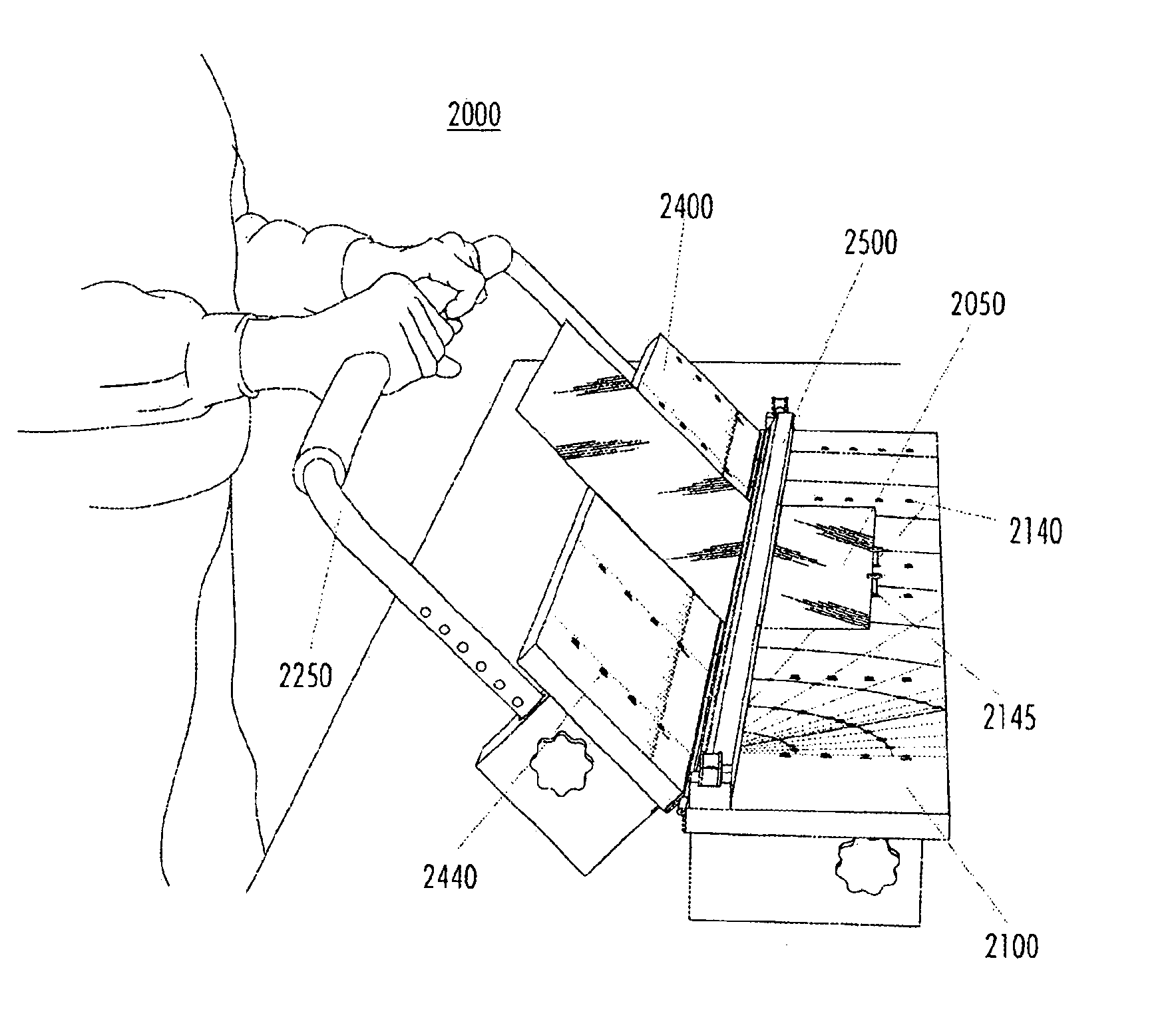
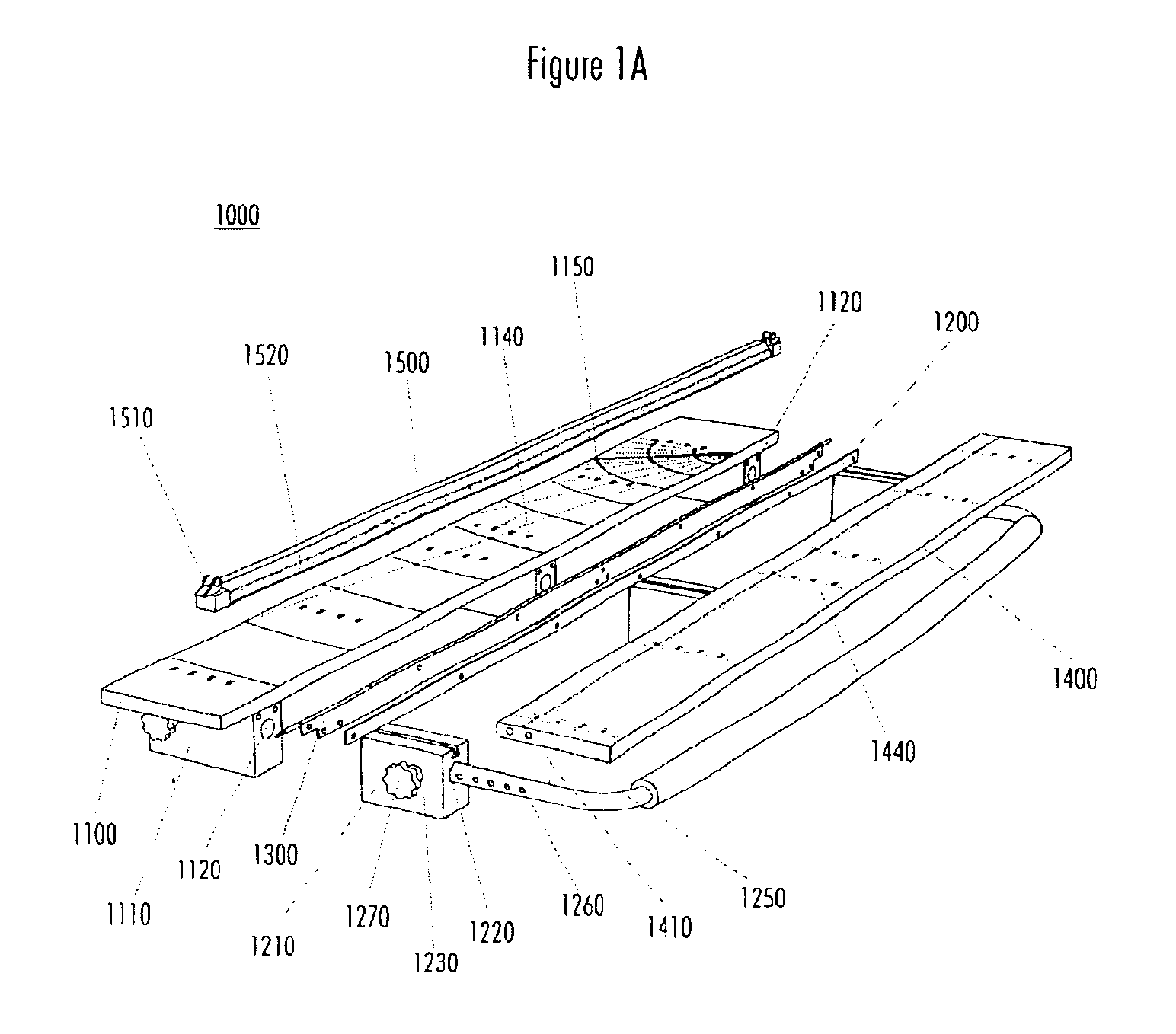
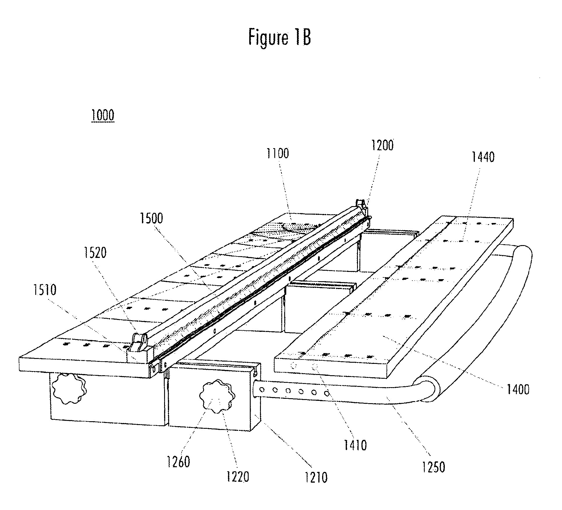
[0032]With respect to FIG. 1A, the metal bending tool 1000 comprises a restraining base 1100 for placing and cooperatively holding a sheet metal workpiece; a bending component 1200 optionally receiving and fixing in position a second base 1400, the bending component rotatably mounted by a hinge 1300 to the restraining base 1100, the bending component and, optionally, the second base 1400 cooperatively holding the metal workpiece in conjunction with the restraining base 1100. The restraining base 1100 is adapted to receive a clamp arm 1500 for holding and stabilizing the workpiece while the workpiece is bent by the rotating action of the bending component 1200.

[0033]The bending component 1200 has a handle 1250 that is used by an operator to bend a metal workpiece. The handle 1250 is received by a hole 1220 drilled through each handle block 1210 of the bending component 1200. Each hole 1220 is drilled completely through the handle block 1210 so that the ends of the handle 1250 may be ...


PUM

PropertyMeasurementUnit
angleaaaaaaaaaa
bending anglesaaaaaaaaaa

Abstract

A sheet metal bending tool for bending materials, such as flat metal sheets is disclosed. The tool has a restraining base for receiving and cooperatively holding a sheet metal workpiece and the tool has a bending component that is rotatably mounted to the restraining base, the workpiece is held, cooperating with the restraining base component, and the clamp bar for stabilizing the workpiece while the workpiece is held and bent by the rotating action of the bending component. In the preferred embodiment, the workpiece is restrained by a template comprising a pattern of holes drilled, a hole receiving a peg or means of stop, the stops (pegs) constraining the workpiece from movement while being bent act like a jig for measuring and predetermined incumbents. Holes are also drilled in restraining base and in the bending component at spaced intervals along lines that are run parallel to the line defined by the intersection of the bending component and the restraining base. There is a pull back bar that is used for the process of cutting. The Unit can be clamped down also. Rulers are installed on the clamp bar, and the slide table. The apparatus is designed so that two or more may be joined together to form a larger apparatus for the purpose of bending larger workpieces.

Description

RELATED APPLICATIONS[0001]This application is related to and derives priority from U.S. Provisional Application No. 60 / 376,525, entitled PORTABLE MINI-BREAK, filed May 1, 2002, which is incorporated herein by reference.BACKGROUND[0002]1. Field of the Invention[0003]This invention relates to metal-forming and shaping tools, and more particularly to manually operable metal-bending devices of the type especially adapted to impart any of a number of predetermined shapes to metal stock, or other materials.[0004]2. Current Art[0005]In the past, numbers of tools for performing a variety of bending operations on metal stock have been proposed and produced, and have met with varying degrees of success.[0006]However, and examination of these devices reveals several limitations of these tools; they are complex to use, expensive to make, bulky and non-portable.SUMMARY[0007]With the aforementioned limitations in mind, it is a general object of the invention to provide a tool for bending sheet me...

Claims


Application Information

Patent Timeline
Patent Type & Authority Patents(United States)
IPC IPC(8): B21D11/00B21D5/00
CPCB21D5/00B21D11/00
Inventor PERRUCCIO, DANIEL
Owner PERRUCCIO DANIEL
Why Eureka
Try Eureka