Eureka AIR delivers breakthrough ideas for toughest innovation challenges, trusted by R&D personnel around the world.

Field configurable electric strike for exit devices

a field configurable, electric strike technology, applied in the direction of building locks, construction, fastening means, etc., to achieve the effect of reducing the number of strikes, reducing the cost of strikes, and reducing the number of return trips

Inactive Publication Date: 2005-08-09
OXLEY RANDALL C
View PDF21 Cites 17 Cited by
  • Summary
  • Abstract
  • Description
  • Claims
  • Application Information

AI Technical Summary

Benefits of technology

[0013]Advantages of the invention include: its size; its ability to be field configured for fail-safe and fail-secure operation; its ease of installation in any application; and its keeper. The keeper attends to the rotation of the aforementioned Dor-O-Matic (trademark) latch back to its locked position as it is itself rotated back to its own locking position. This eliminates the jamming problem that plagues prior devices. The new strike is smaller and mounts in required applications without modification. The strike is designed to simplify installation: all necessary cutting is done forward of the door stop rib. This satisfies a major complaint of prior device installers who have difficulty measuring and cutting over and through the doorstop. The strike, when installed, is to be adorned by a finished trim plate. These trim plates can be easily and cheaply stamped out of sheet metal in any architectural finish requested. This solves the problem of having to sand or paint the prior device's strike body in its entirety.
[0015]The invention addresses these problems for the manufacturer, distributor, and installer. It permits one strike body to be used in any application just by selecting the correctly finished trim plate to match the order. Because the trim plates are inexpensive, the distributor and installer can stock a variety of them at a comparatively minimal cost. This allows the installer to carry fewer strikes to the job-site, and have fewer return trips per job. This also allows the distributor to sell a greater volume of strikes with less per piece special attention required filling orders. This also allows the manufacturer to benefit from fewer “rush order” interruptions to their normal production cycle. All of these features are a distinct improvement over prior devices. All of these features result in a more volume and profits for the manufacturer, distributor, and the installer.
[0016]Since the mechanism developed for this strike is relatively compact, it can be used in other embodiments, such as a rim panic strike, a 161 prep strike, and an ANSI standard size strike, among others. Installation of a typical rim panic strike requires cutting out a portion of the hollow metal door jamb to accommodate the mechanism or body of the strike, and often the door jambs are concrete filled. The concept of a flush mounted rim strike for an exit device is relatively new, but not novel. Prior patented rim strikes are generally larger, thicker, and longer than the strikes they are replacing. The invention makes possible a rim panic strike that can be very flat and small enough to replace the standard typical roller strike that comes as standard equipment for most exit devices. This results in a strike that will mount, using the same mounting screw holes as the non-electric roller strike, and that can be installed in matter of seconds, without any cutting, by anyone who can use a screwdriver.
[0017]The invention can be made small enough to fit the old standard jamb cutout (161 prep) that is 2¾″×1⅛″. This configuration, also referred to as the “T” strike cutout, is used widely in residential applications and almost exclusively in the modular office wall partition systems used today. Since the solenoid is housed within the small strike body, the normal extra depth cutout is not required. This saves labor time and expense during installation, and also preserves the structural integrity of the door jamb. This is especially important in residential applications that feature wooden doorjambs. In most electric strike installations, it is necessary to cut away the doorjamb to permit the latch a means of passage when opening the door. This is labor intensive, and can be unsightly in residential and commercial applications where there are fancy wooden or steel door casings that have to be cut out. When this new strike is installed with the accompanying special faceplate, any cutout for a raceway is not necessary. The small strike and ANSI embodiments will use a specially designed face plate that features a ramp for the latch to travel up and over the lip of the face plate without necessitating any further cutting. This ramp has a special shape that accommodates the auxiliary latch, which normally serves to block the latch from being “ramped” back into the door. This special faceplate will benefit the user in at least three ways. It will save time and expense of labor normally needed for installation of the strike. It will improve the appearance of the strike in the doorjamb and preserve the esthetic integrity of the existing door casing. Finally, it will improve the security of the door latch and lock by eliminating the need for a large “raceway” for the latch. Raceways usually serve to provide an opportunity for tool attack by anyone seeking to pry back the latch to bypass the door locking system.

Problems solved by technology

This satisfies a major complaint of prior device installers who have difficulty measuring and cutting over and through the doorstop.

Method used


Image

  • Field configurable electric strike for exit devices
  • Field configurable electric strike for exit devices
  • Field configurable electric strike for exit devices

Examples


Embodiment Construction

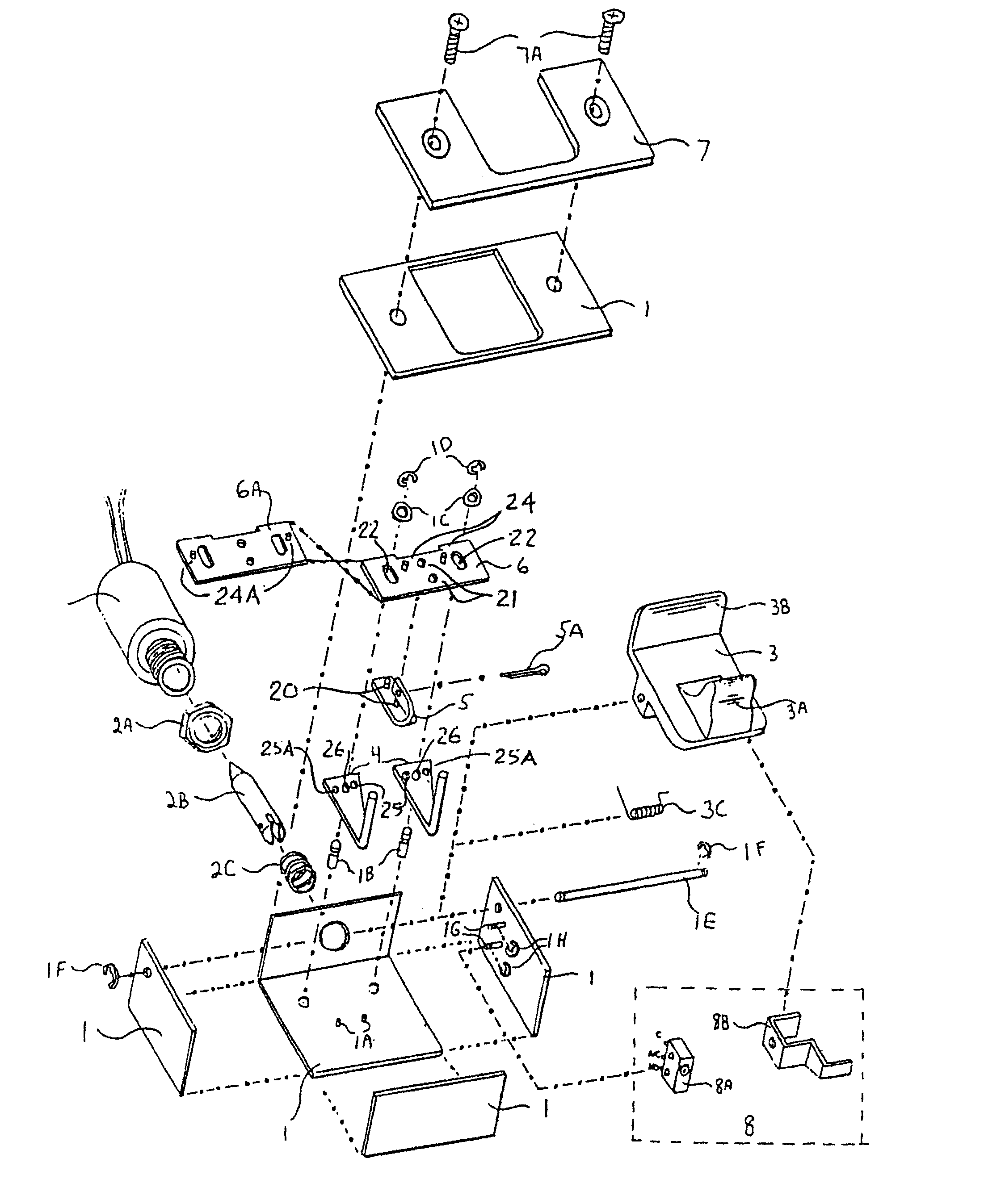
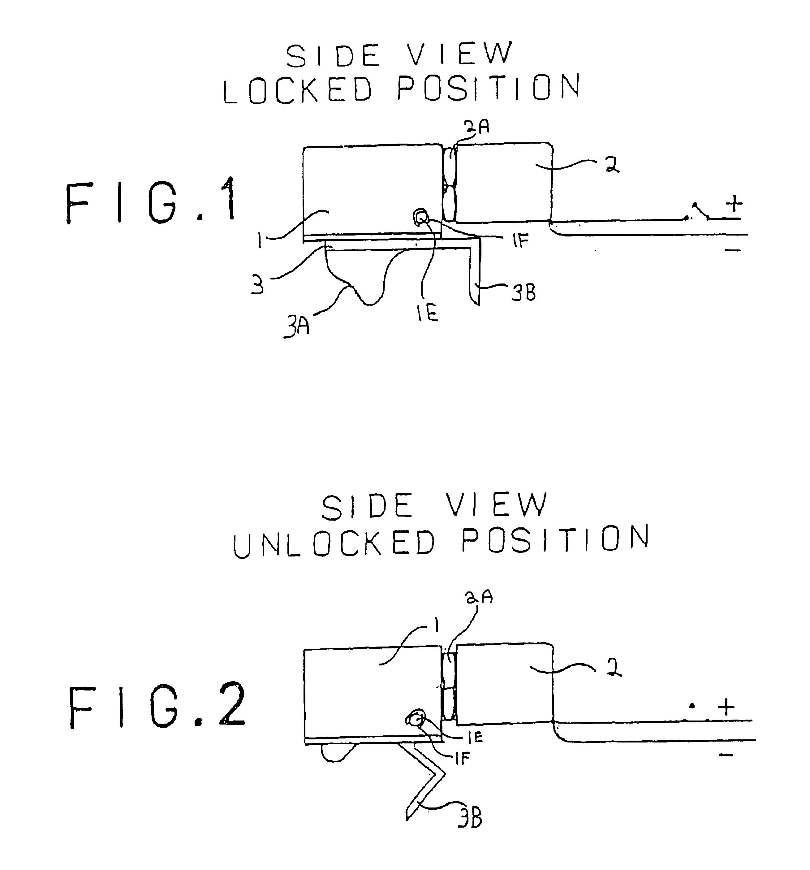
[0045]FIG. 1 is a side schematic view of an electric strike, according to the present invention, as it would be typically mounted in a door header or jamb. This figure shows the external view of the assembly of parts, in its preferred embodiment, comprised of the strike body 1, a solenoid 2 which is threaded into the body 1 and fastened into place by a lock nut 2A. A keeper 3 which rotates about an axle 1E and extends below the body 1 so as to engage a door latch or plate in the top or side of a door. The axle passes through the strike body 1 and is centered therein by retainer clips 1F at either end. The view also shows the reverse contour 3A and the relocking lever 3B features of the keeper.

[0046]FIG. 2 shows the strike of FIG. 1 with the keeper 3 (which is spring biased toward the released position) in the released position.

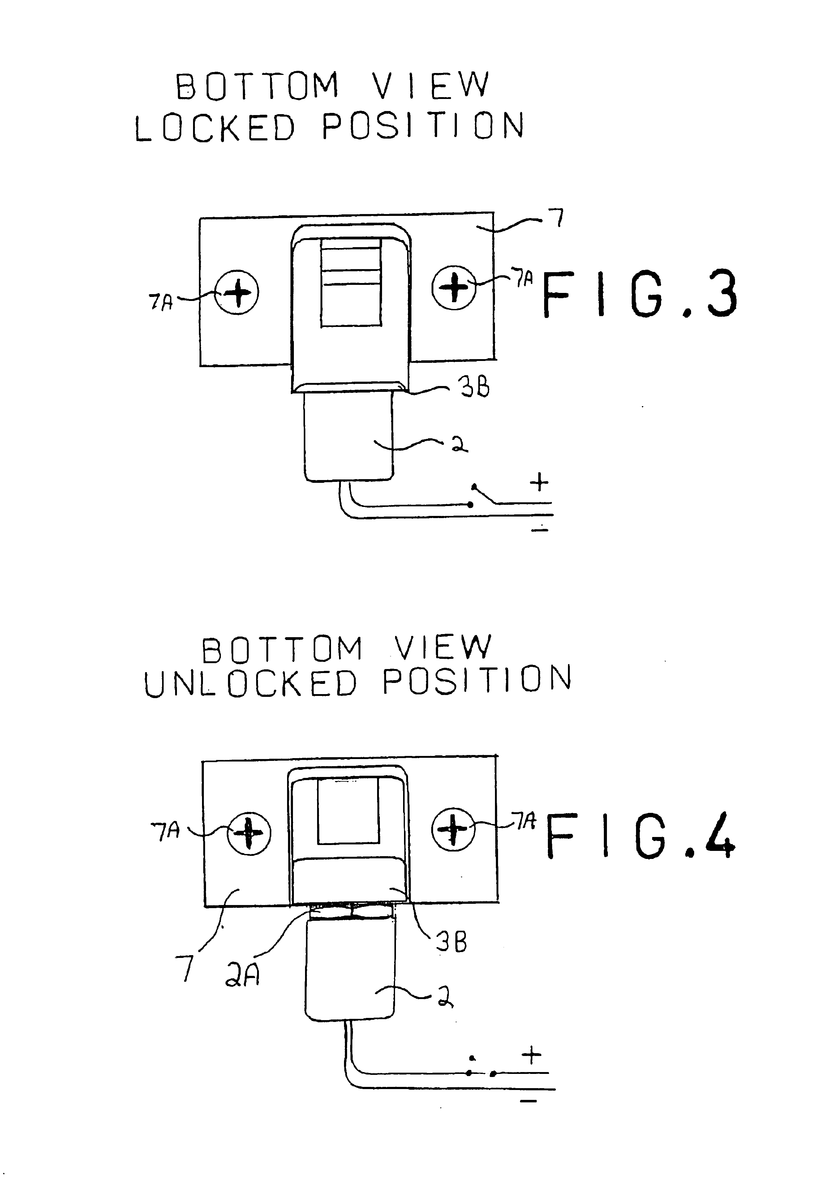
[0047]FIG. 3 illustrates the preferred embodiment from a bottom view in the locked position.

[0048]FIG. 4 shows the strike of FIG. 3 in the unlocked position.

[...


PUM


Abstract

This electric strike mechanism has a housing, a keeper pivotally mounted in the housing, at least one locking element pivotally mounted within the housing, for pivoting between a first position where the keeper is prevented from pivoting, and a second position where the keeper is permitted to pivot so that the door can be opened, a solenoid connected to each locking element via an actuation mechanism to move each locking element when the solenoid is energized, and a spring biasing the solenoid towards a non-actuated position. The actuation mechanism may be installed in one of two orientations, namely a first (fail-secure) orientation wherein the locking element is in its first position when the solenoid is not energized and wherein energizing the solenoid moves the locking element to the second position, and a second (fail-safe) orientation wherein the locking element is in the second position when the solenoid is not energized and wherein energizing the solenoid moves said locking element to the first position.

Description

REFERENCE TO RELATED APPLICATION[0001]This is a formal application based on and claiming the benefit of U.S. provisional patent application No. 60 / 402,748, filed Aug. 12, 2002.BACKGROUND OF THE INVENTION[0002]This invention relates to an electric strike that is small enough to be used in multiple applications and can be configured in the field for fail-safe or fail-secure operation.[0003]The field of electrically operated strikes is filled with a multitude of devices, which essentially do the same thing: they release a latch that extends into the body of the strike so as to open the door that contains the latch. They commonly use a solenoid which, through some mechanical linkage, will release the keeper holding the latch and then return to its locked condition after the latch is released. There are very few electric strikes whose keeper extends into a latch contained within the door and, upon energizing, not only rotates out of the latch, but also remains in its rotated condition un...

Claims


Application Information

Patent Timeline
Patent Type & Authority Patents(United States)
IPC IPC(8): E05B47/00
CPCE05B47/0047E05B2047/0073E05B2047/0076Y10T292/1082Y10T292/1062Y10T292/699
Inventor OXLEY, RANDALL C.
Owner OXLEY RANDALL C
Why Eureka
Eureka Blog
Learn More