Toy rocket launch pad with directional safety valve

a safety valve and rocket launcher technology, applied in the field of toy rocket launchers, can solve the problems of affecting the operation of the operator or spectator, the use and function of each rocket being typically limited, and the danger of solid fuel, etc., to achieve simple and durable construction, facilitate storage, transportation and packaging, and reduce the effect of labor intensity

Active Publication Date: 2005-08-09
RAPPAPORT MARK
View PDF10 Cites 9 Cited by
  • Summary
  • Abstract
  • Description
  • Claims
  • Application Information

AI Technical Summary

Benefits of technology

[0011]The launcher of the present invention provides an advantage of an integrated, directional safety valve for providing a simple, cost efficient and effective apparatus that avoids high velocity launch of a toy rocket in other than a vertical direction.
[0012]Further, the present invention provides a launcher of simple and durable construction that can be provided on a single operating platform to facilitate easy storage, transport and packaging, without loss of the safety feature.

Problems solved by technology

Numerous types of toy rocket launchers are known in the art, with the usefulness and function of each being typically limited by the construction, manner of propulsion and arrangement of the various elements of the launcher and rocket.
Solid fuel can be dangerous, and if improperly used can cause serious harm to the operator or to spectators.
Although less dangerous than rockets having solid fuel propulsion systems, misuse of conventional pressure-propelled rocket launchers can result in injury.
Such injury can arise when the toy rockets are launched in a horizontal, rather than a vertical direction.

Method used


Image

  • Toy rocket launch pad with directional safety valve
  • Toy rocket launch pad with directional safety valve
  • Toy rocket launch pad with directional safety valve

Examples


Embodiment Construction

[0024]The following detailed description of the preferred embodiments of the invention makes reference to the accompanying drawings. In describing the invention, explanation of related functions or constructions known in the art are omitted for the sake of clearness in understanding the concept of the invention, to avoid obscuring the description of the invention with unnecessary detail.

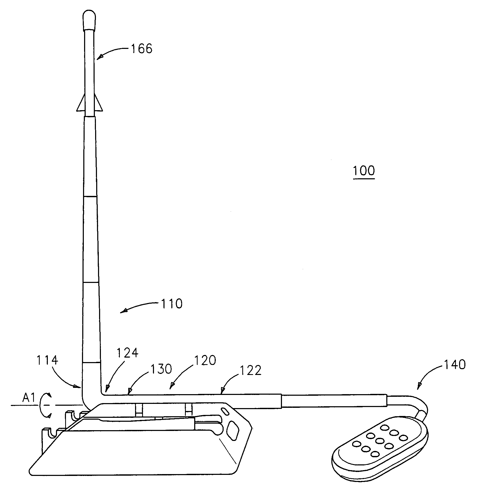
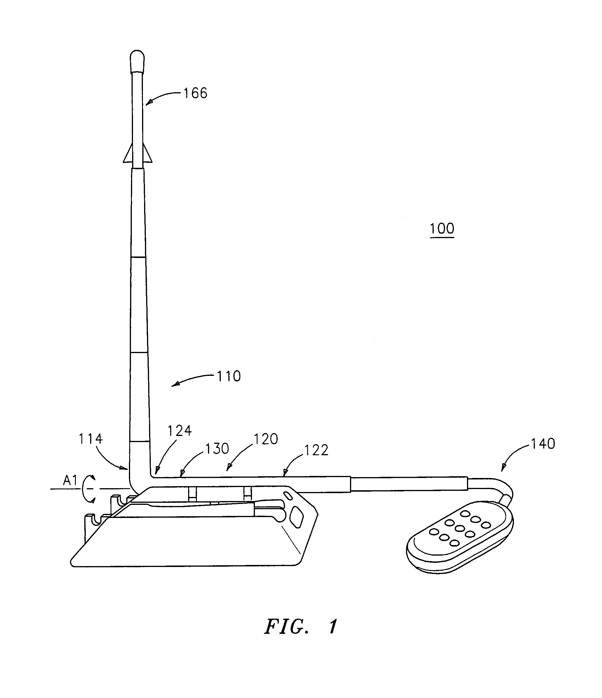
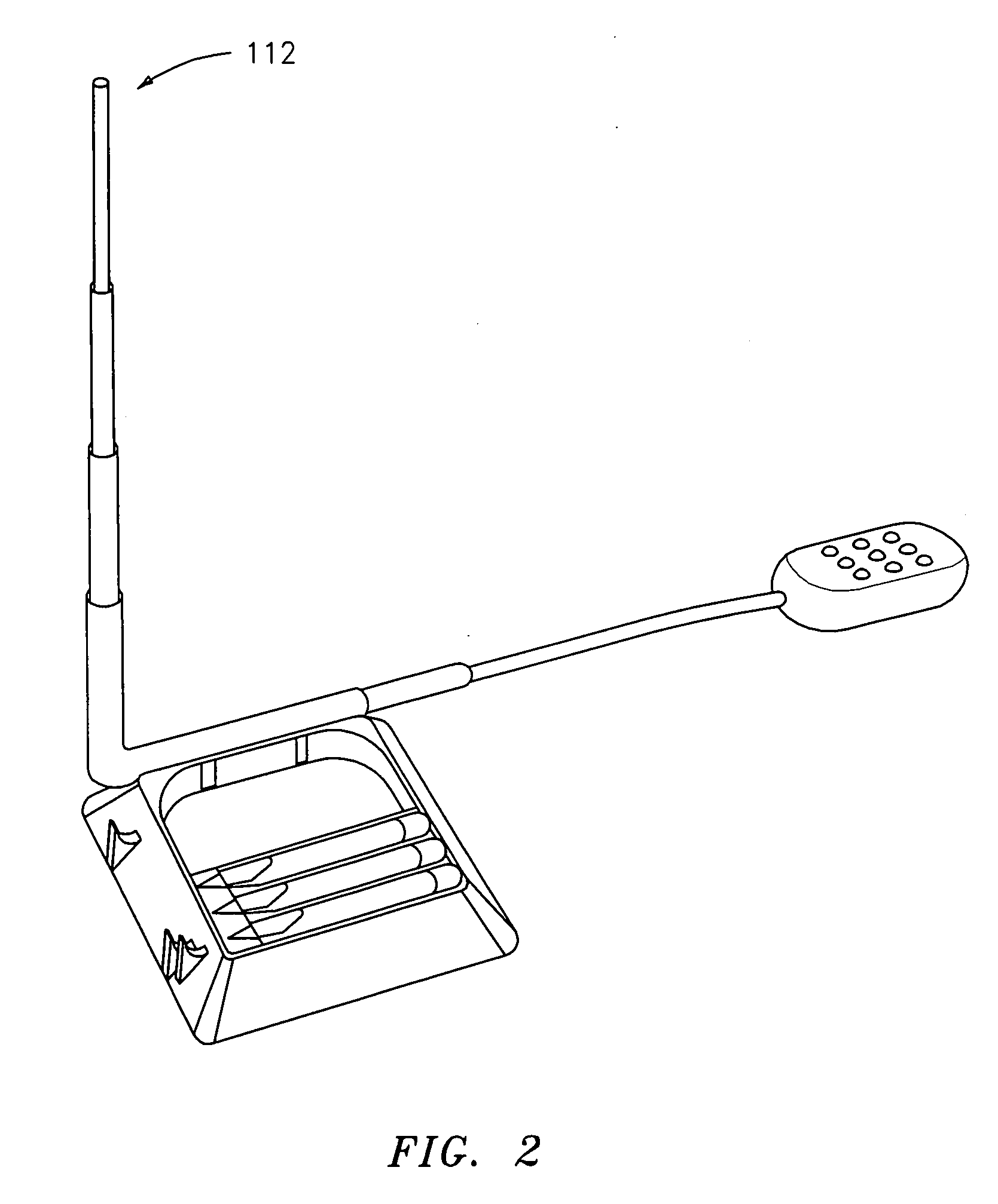
[0025]FIGS. 1 and 2 are perspective views of launcher 100 of the present invention. Launcher 100 includes a launch tube 110 rotatable about axis A1. A connecting tube 120 is coaxially provided about axis A1. The connecting tube 120 serves as an air channel by connecting at a first end 122 to a device or chamber, such as a bellows 140, which provides a pressurized pulse of air or water for launching a toy rocket 166 (not shown in FIG. 2).

[0026]The connecting tube 120 rotatably connects, at a second end 124 thereof, to the launch tube 110. The rotatable connection between the connecting tube 120 and th...


PUM


Abstract

Disclosed herein is an apparatus and method for launching a toy rocket that includes rotating a launch tube about an axis that is parallel with a connecting tube, which is rotatably connected to the launch tube; extending the launch tube in a perpendicular direction; progressively closing a safety valve by rotating the launch tube toward a vertical position, relative to a launch pad assembly; loading the toy rocket onto a distal end of the extended launch tube; and rapidly compressing a bellows in communication with the launch tube.

Description

PRIORITY[0001]The application claims priority to provisional application Ser. No. 60 / 496,203, which was filed with the U.S. Patent and Trademark Office on Aug. 19, 2003, the contents of which are incorporated herein by reference.BACKGROUND OF THE INVENTION[0002]1. Field of Invention[0003]The present invention relates generally to a toy rocket launcher and, more particularly, to a toy rocket launcher which is actuated by air or hydraulic pressure.[0004]2. Description of the Related Art[0005]Numerous types of toy rocket launchers are known in the art, with the usefulness and function of each being typically limited by the construction, manner of propulsion and arrangement of the various elements of the launcher and rocket.[0006]Many model rockets use self-propelled, solid fuel rocket engines to propel them into the air. Solid fuel can be dangerous, and if improperly used can cause serious harm to the operator or to spectators.[0007]Less dangerous are pressure-propelled rocket launcher...

Claims


Application Information

Patent Timeline
Patent Type & Authority Patents(United States)
IPC IPC(8): F41B11/00F41F3/04F41B11/24F41F3/00F41B11/66
CPCF41B11/66F41B11/89F41F3/04
Inventor RAPPAPORT, MARK
Owner RAPPAPORT MARK
Why Eureka
Try Eureka