
Gear driven power converter

Inactive Publication Date: 2005-08-09
LUPER JERRY
View PDF28 Cites 91 Cited by
  • Summary
  • Abstract
  • Description
  • Claims
  • Application Information

AI Technical Summary

Benefits of technology

"The present invention is a power converter that can convert a continuous rotary input into a fully variable, stoppable, and reversible rotary output. It has a planar design that can rotate at different speeds. The invention uses a power transfer device for vehicles that uses a rotational power supply. It includes a differential gear that is proportional to a gear ratio coupled speed difference between two rotational bodies. The invention also includes a method for controlling the rotational speed of an output shaft powered by an input shaft. The technical effects of the invention include a consistent balance and operation at variable speeds, as well as a more efficient and flexible power conversion system."

Problems solved by technology

These patents fail to provide a planar power converter for use with a rotary input with a differential speed introduced by a variable speed transmission so that the power converter can convert the speed differential into a power output.

Method used


Image

  • Gear driven power converter
  • Gear driven power converter
  • Gear driven power converter

Examples


Embodiment Construction

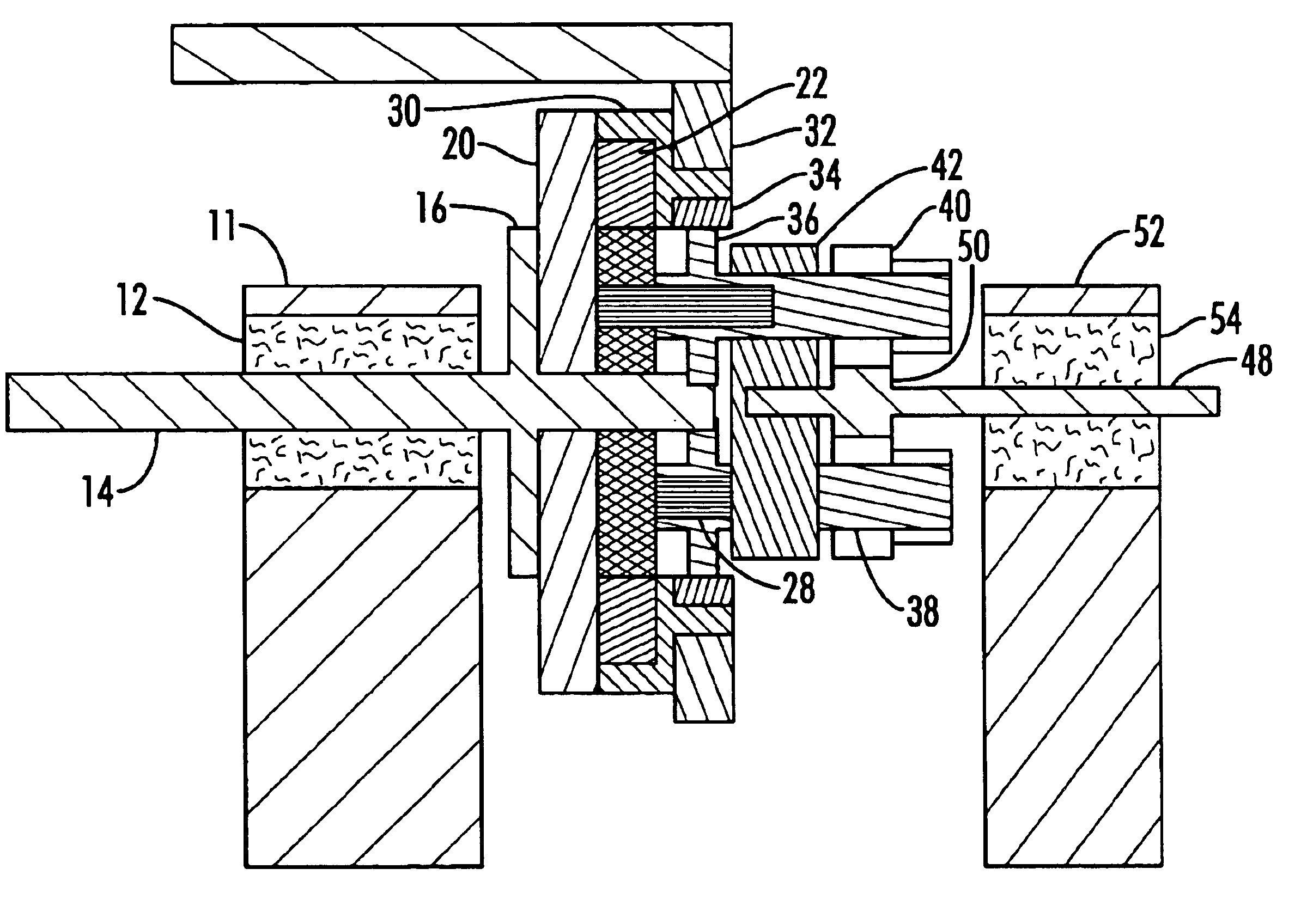
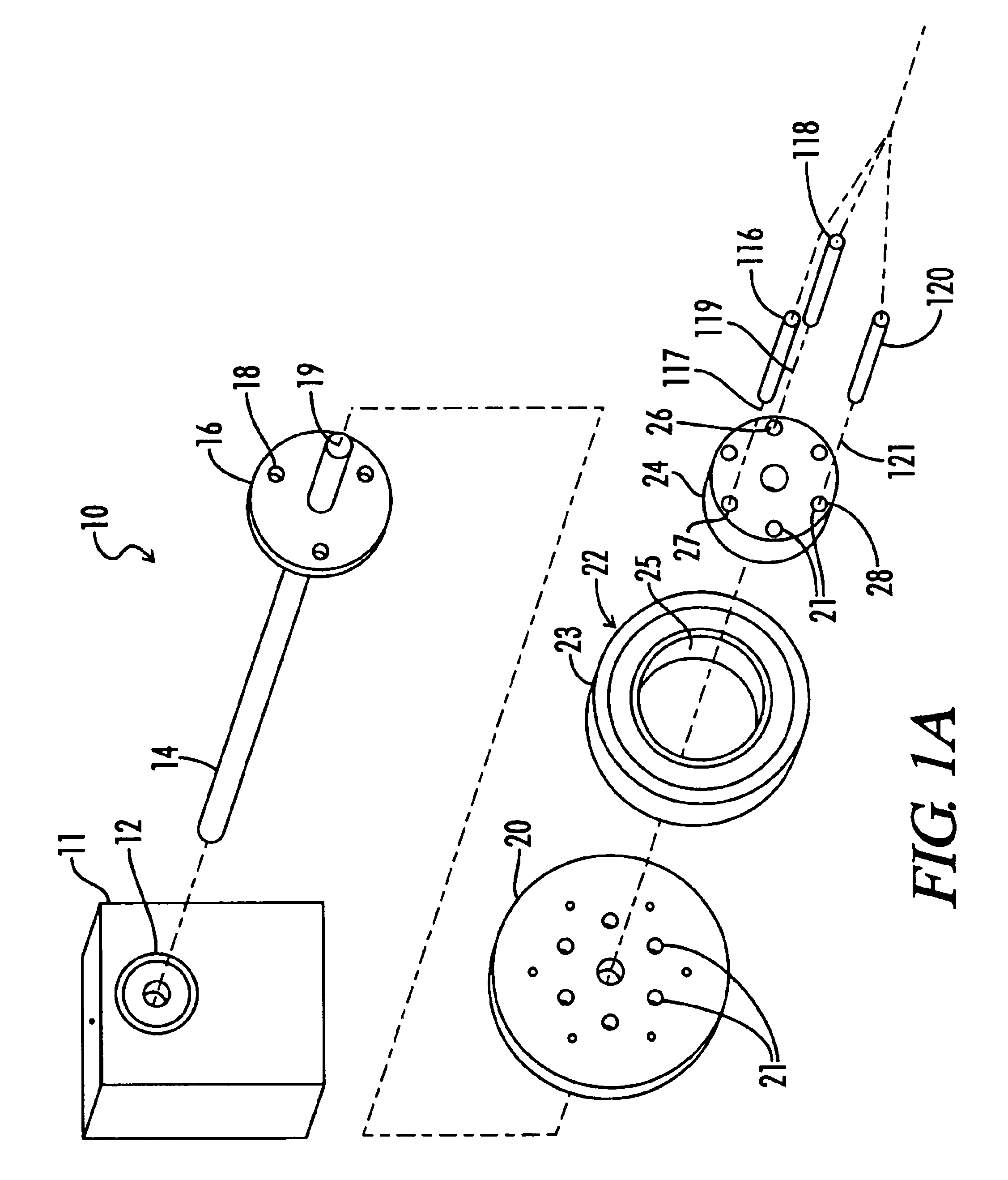
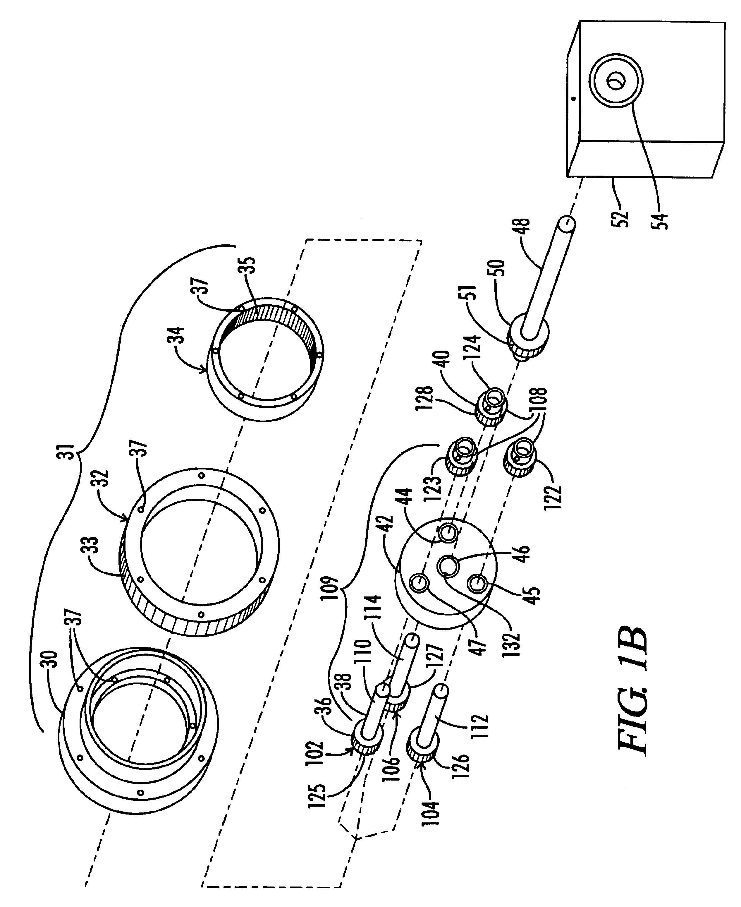
[0019]FIG. 4 of the drawings shows an overview of the placement of the power coupling 10 of the present invention in a power transfer apparatus 401, also known as a drive train 401, for a vehicle. The vehicle includes a rotational power supply 400 that is used to drive the vehicle, such as an internal combustion engine, electric motor, hydraulic drive, centrifugal generator or other method of generating rotational power. The present invention provides a drive train 401 from the rotating power supply 400 to the output 408. The drive train 401 begins with a variable speed transmission 402 adapted to convert the rotational power supply into a first power supply 404, also known as a first rotational power input operating at a first speed, and a second power supply 406, also known as a second rotational power input operating at a second speed. This type of variable speed transmission 402 is well known in the art and has many alternative designs. One of the speeds may simply be a pass thr...


PUM


Abstract

A differential power coupling for generating forward and reverse motions and allowing stopping of the rotation for a vehicle using a rotational power supply to power a variable speed transmission having first and second outputs. The power coupling uses a rotational outside gear with an outside face coupled to the first power supply, a rotational support body coupled to the second power supply and adapted to rotate axles of differential gears around a central axis, and at least one differential gear rotationally mounted on the axle attached to the rotational support body and coupled to the inside face. The differential gear is further coupled to the output shaft and adapted to create a fully variable rotation of the outputs shaft including forward, reverse and stopped rotation. A method is also described for controlling a rotational speed of an output shaft by converting an input rotation into a first and second rotation, differentiating the first rotation and the second rotation to achieve a third rotation; and transferring the third rotation to the output shaft as a function of the difference.

Description

BACKGROUND OF THE INVENTION[0001]The present invention relates generally to variable speed transmissions and more particularly, this invention pertains to a method of variably driving a rotary output from a constant rotary input with a power converter.[0002]Variable speed transmissions are well known in the art. Examples of these are illustrated in the prior art patents including: U.S. Pat. No. 6,068,570 entitled “Variable Speed Transmission System And Differential”; U.S. Pat. No. 5,308,293 entitled “Variable Speed Drive Transmission”; U.S. Pat. No. 5,116,292 entitled “Variable Drive Transmission”; U.S. Pat. No. 5,108,352 entitled “Modified Cranking Mechanism For Epicyclic Transmission”; U.S. Pat. No. 4,983,151 entitled “Transmission Ratio Changing Apparatus And Method”; U.S. Pat. No. 4,112,778 entitled “Variable Speed Power Transmission”; U.S. Pat. No. 3,955,435 entitled “Variable Speed Drive Mechanism”; U.S. Pat. No. 3,087,355 entitled “Constantly Variable Speed Transmission”; U.S...

Claims


Application Information

Patent Timeline
Patent Type & Authority Patents(United States)
IPC IPC(8): F16H3/72F16H3/44
CPCF16H3/72
Inventor LUPER, JERRY
Owner LUPER JERRY
Learn More