Video signal processing circuit and method for converting number of scan lines and image display device using the same
a video signal and signal processing circuit technology, applied in the direction of signal generators with optical-mechanical scanning, color signal processing circuits, television systems, etc., can solve the problems of inability to actually adopt band limiting, image quality degradation, and inability to achieve band limiting, etc., to achieve high image quality and convenient for users
- Summary
- Abstract
- Description
- Claims
- Application Information
AI Technical Summary
Benefits of technology
Problems solved by technology
Method used
Image
Examples
first embodiment
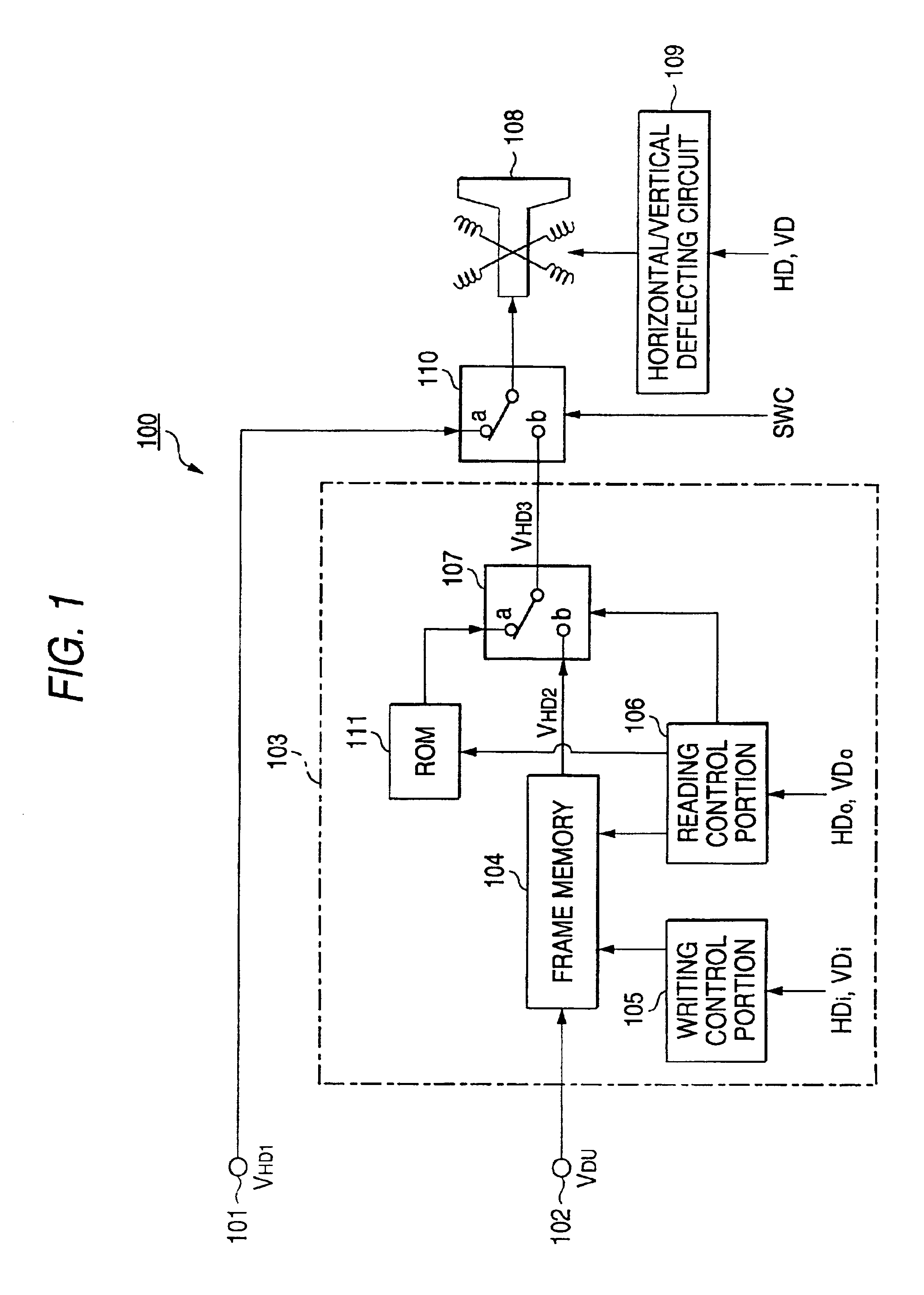
[0054]FIG. 1 shows the construction of an image display device 100 according to the present invention.
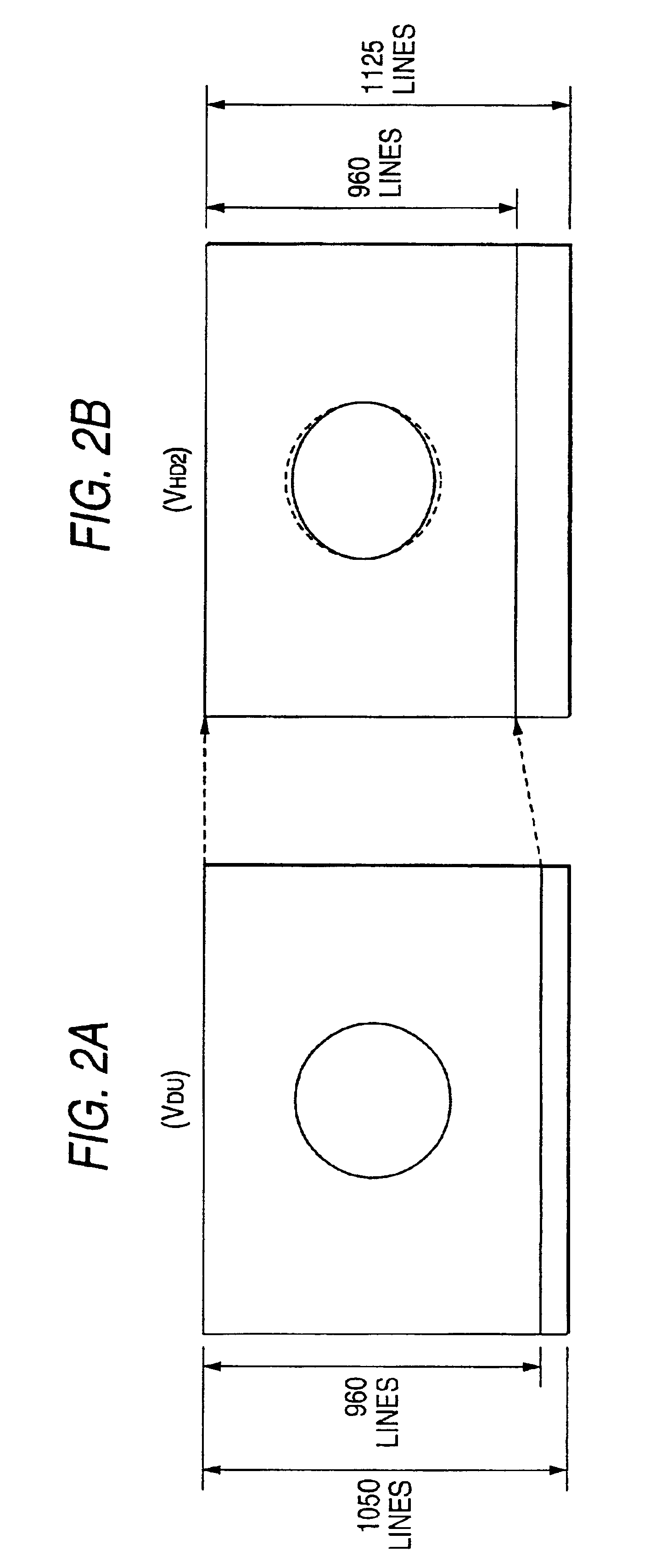
[0055]The image display device 100 has an input terminal 101 to which an HDTV signal VHD1 is input, and an input terminal 102 to which a double-rate signal VDU is input. Here, the vertical scan line number (the number of vertical scan lines) of the HDTV signal is equal to 1125 (the effective scan line number is equal to 1080). The double-rate signal VDU is achieved by subjecting a video signal of EDTV-II system to double-rate conversion, and the vertical scan line number (the number of vertical scan lines) of the double-rate signal is equal to 1050 (the effective scan line number is equal to 960).
[0056]The image display device 100 has a scan line number converting portion 103 for achieving an HDTV signal VHD3 from the double-rate signal VDU input to the input terminal 102.
[0057]The scan line number converting portion 103 comprises a frame memory 104, a writing control portion 105, a...
second embodiment
[0069]Next, a second embodiment according to the present invention will be described.
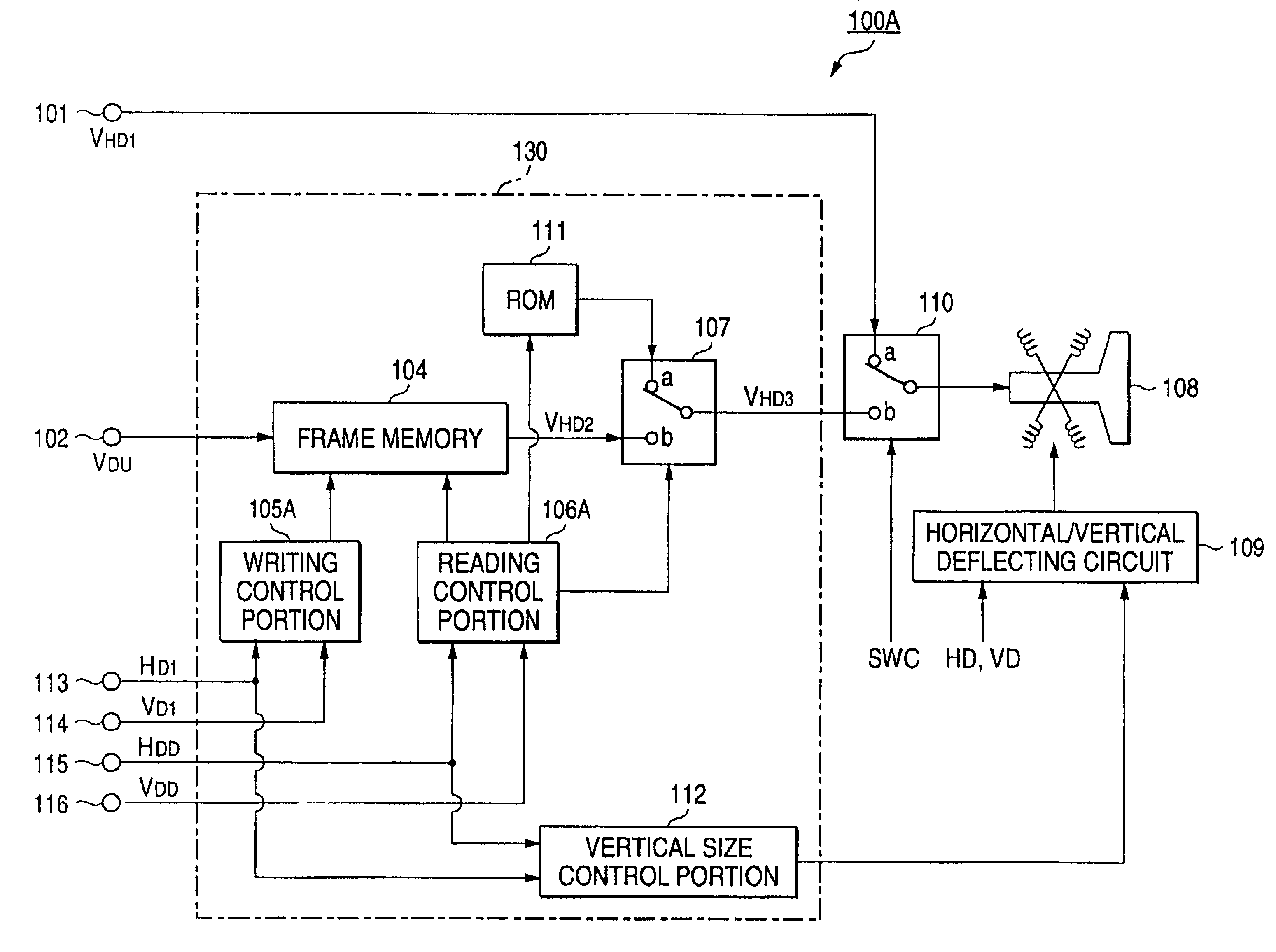
[0070]FIG. 3 shows the construction of an image display device 100A according to the second embodiment of the present invention. The image display device 100A is designed so that the contraction in the vertical direction of the image as described above is prevented. In FIG. 3, the corresponding portions to those of FIG. 1 are represented by the same reference numerals, and the detailed description thereof is omitted.
[0071]The image display device 100A has a scan line number converting portion 130 for achieving an HDTV signal VHD3 from a double-rate signal VDU input to the input terminal 102.
[0072]The scan line number converting portion 130 is equipped with a writing control portion 105A for writing the portion of 960 effective scan lines of the double-rate signal VDU into the frame memory 104 every frame, a reading control portion 106A for reading out the portion of 960 effective scan lines of the d...
third embodiment
[0076]Next, a third embodiment according to the present invention will be described.
[0077]FIG. 4 shows the construction of an image display device 100B according to a third embodiment of the present invention. In FIG. 4, the corresponding portions to those of FIG. 1 are represented by the same reference numerals, and the detailed description thereof is omitted.
[0078]The image display device 100B shown in FIG. 4 has an effect of preventing occurrence of contraction in the vertical direction of the image based on the HDTV signal VHD2 achieved by the scan line number converting portion 103 as in the case of the image display device 100A shown in FIG. 3.
[0079]The image display device 100B has a horizontal pixel number converting circuit 120 for reducing the number of pixel signals of each scan line constituting the HDTV signal VHD3 output from the scan line number converting portion 103 and achieving an HDTV signal VHD4 in which each of the pixel signals of each scan line concerned is s...
PUM
 Abstract
Description
Claims
Application Information
 - R&D
- Intellectual Property
- Life Sciences
- Materials
- Tech Scout
- Unparalleled Data Quality
- Higher Quality Content
- 60% Fewer Hallucinations
Browse by: Latest US Patents, China's latest patents, Technical Efficacy Thesaurus, Application Domain, Technology Topic, Popular Technical Reports.
© 2025 PatSnap. All rights reserved.Legal|Privacy policy|Modern Slavery Act Transparency Statement|Sitemap|About US| Contact US: help@patsnap.com


