Flanging processes with radial compression of the blank stretched surface
- Summary
- Abstract
- Description
- Claims
- Application Information
AI Technical Summary
Benefits of technology
Problems solved by technology
Method used
Image

Examples
Embodiment Construction
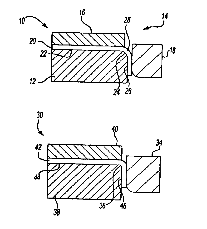
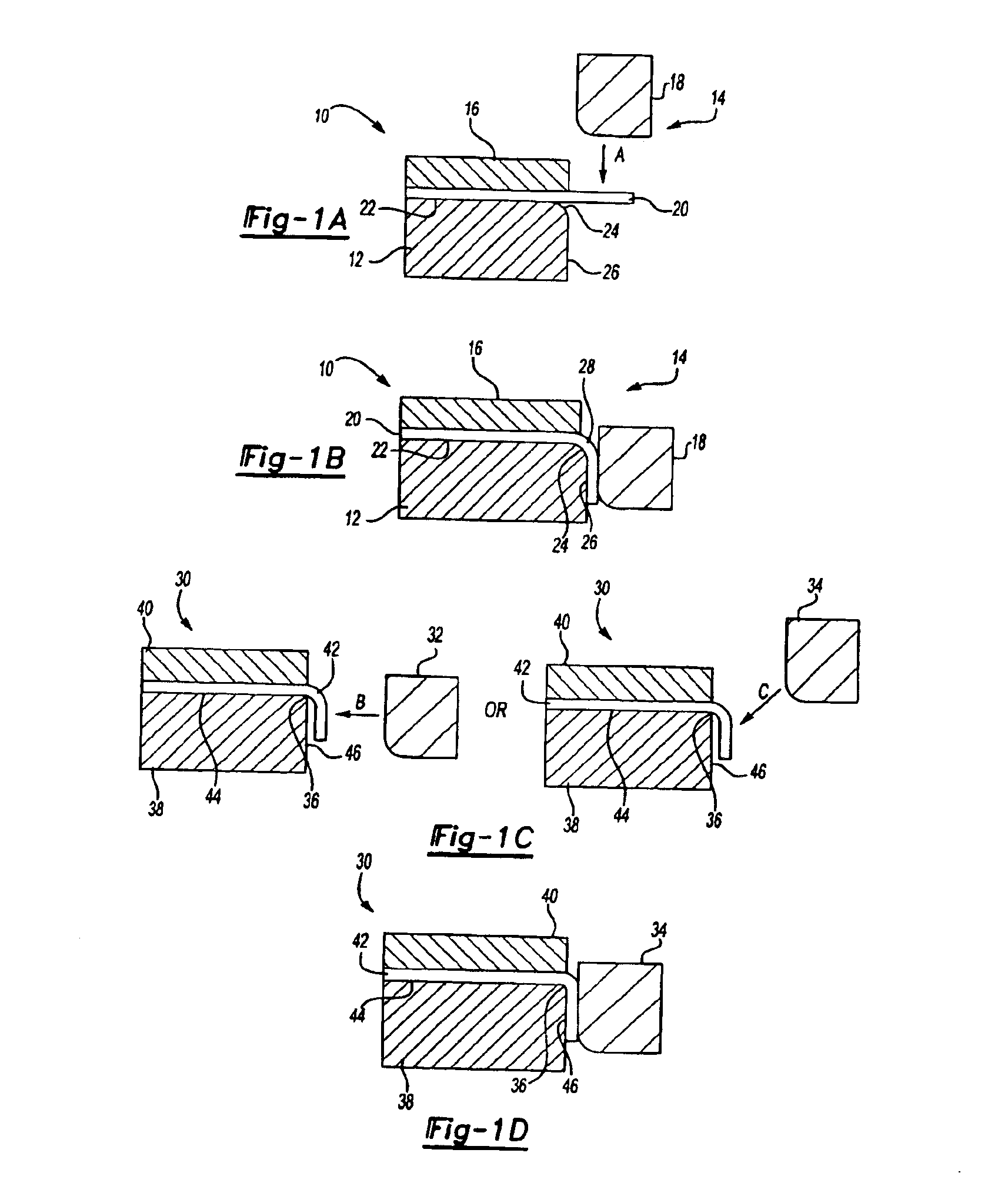
[0017]Referring now to the drawings, FIGS. 1A through 1D are related as steps in a process for forming a flange on a panel for a hem. In FIG. 1A pre-flange tool 10 is shown to include a lower die 12 and an upper die 14. Upper die 14 includes a clamping portion 16 and a bending member 18, or flanging punch. The clamping portion 16 clamps the sheet metal blank 20 to the lower die 12 during pre-flange process. Bending member 18 acts on a peripheral portion of the sheet metal blank 20. Bending member 18, as indicated by the directional arrow “A”, wipes the sheet metal blank 20 to form it against the lower die 12. Lower die 12 includes a supporting portion 22 that supports the sheet metal blank 20 and a large radius portion 24 over which the sheet metal blank 20 is initially formed to impart a larger radius bend in the sheet metal blank 20. A forming portion 26 of the lower die 12 is a surface against which the sheet metal blank 20 is formed as the bending member 18 forces it against the...
PUM
| Property | Measurement | Unit |
|---|---|---|
| Thickness | aaaaa | aaaaa |
| Radius | aaaaa | aaaaa |
Abstract
Description
Claims
Application Information
 - Generate Ideas
- Intellectual Property
- Life Sciences
- Materials
- Tech Scout
- Unparalleled Data Quality
- Higher Quality Content
- 60% Fewer Hallucinations
Browse by: Latest US Patents, China's latest patents, Technical Efficacy Thesaurus, Application Domain, Technology Topic, Popular Technical Reports.
© 2025 PatSnap. All rights reserved.Legal|Privacy policy|Modern Slavery Act Transparency Statement|Sitemap|About US| Contact US: help@patsnap.com