Motion compensation system and method

a technology of motion compensation and structure, applied in the direction of floating buildings, sealing/packing, borehole/well accessories, etc., can solve the problems of affecting the safety of coiled tubing well work. , to achieve the effect of safe and safe operation of coiled tubing well work

Inactive Publication Date: 2005-08-16
DEVIN INT
View PDF12 Cites 28 Cited by
  • Summary
  • Abstract
  • Description
  • Claims
  • Application Information

AI Technical Summary

Benefits of technology

[0017]An advantage of the present invention is that the system and method can be used on floating platforms. Another advantage is that the system and method provides for motion compensation on a well undergoing well intervention and remedial well work. Still yet another advantage is that the present invention allows for performing coiled tubing well work safely.
[0018]A feature of the present invention includes the modular design of the components. The modularity allows for ease of transportation, delivery and rig up. Yet another feature includes the ability to build the height needed on specific well applications by simply stacking spacers one on top of the other.
[0019]Another feature is that motion compensation is provided in the vertical direction. Yet another feature is the pressure control means that regulates the pressure to the cylinders. Still another feature is the use of the plurality of posts that guide the frame structure with respect to the deck during movement of the platform.

Problems solved by technology

In deep water, a fixed leg type platform is generally not an option due to the extreme water depths.
In the deep water drilling of subterranean reservoirs, drillers encounter numerous operational problems.
Also, tidal conditions may cause a variation in platform height and cause similar buoyant forces.
While an operator is in the midst of performing well work, the motion of the platform can have detrimental effects on the equipment and ongoing operations.
This motion could potentially cause serious damage such as breaking the connection of the coiled tubing to the riser which in turn could lead to a catastrophic failure.

Method used


Image

  • Motion compensation system and method
  • Motion compensation system and method
  • Motion compensation system and method

Examples


Embodiment Construction

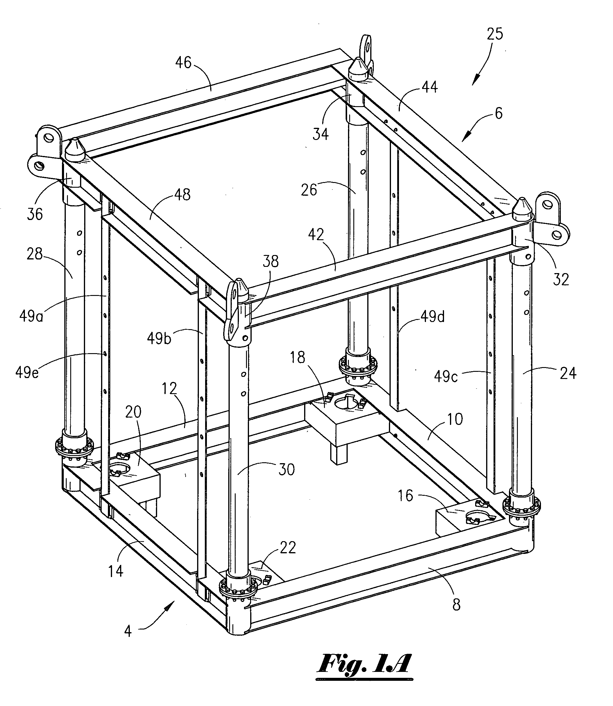
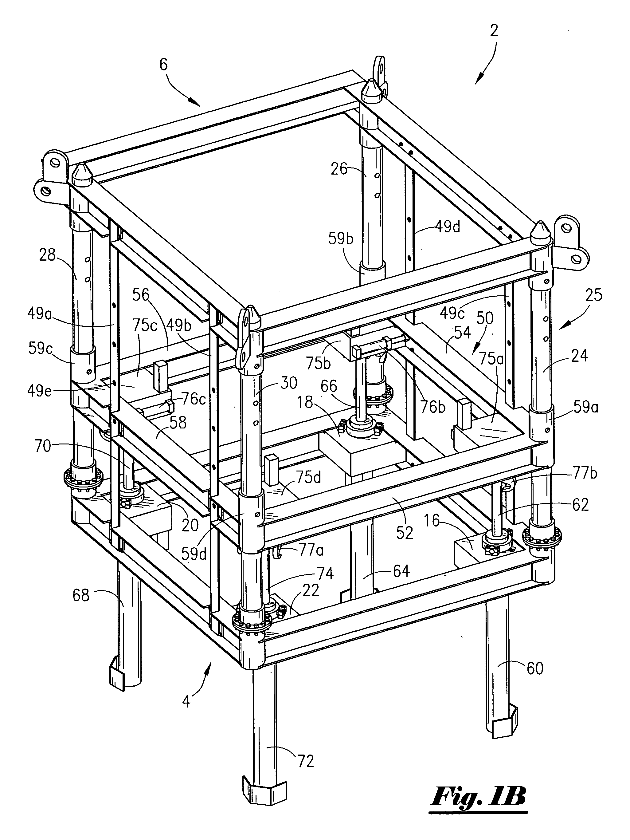
[0033]Referring now to FIG. 1A, an isometric view of the frame member 25 that includes the base support member 4 and the top support member 6 of the present invention shown in a first position. The support member 4 is rectangular member that has four sides namely a first beam 8, second beam 10, third beam 12 and fourth beam 14. At the corners of support member 4 are attachment plates, namely attachment plate 16, attachment plate 18, attachment plate 20 and attachment plate 22. The base support member 4, top support member 6 and associated connecting beams is referred to as the frame member 25.

[0034]FIG. 1A shows that extending from the corner of beams 8, 10 is the post 24; extending from the corner of beams 10, 12 is the post 26; extending from the corner of beams 12, 14 is the post 28; and, extending from the corner of beams 8, 14 is the post 30. The post 24 is disposed through the collar 32; the post 26 is disposed through the collar 34; the post 28 is disposed through the collar ...


PUM


Abstract

A system for providing motion compensation of a platform attached to an ocean floor. The platform is operatively associated with a riser extending from a subterranean well. The system comprises a frame member positioned on the platform and a deck slidably attached to the frame member, and wherein the deck is attached to the riser. The system further comprises a moving device for moving the frame member relative to the deck. In one of the preferred embodiments, the frame member contains a plurality of guide post and wherein the deck is slidably mounted on the guide post so that the frame member is movable relative to the deck. The moving device may comprise a cylinder member operatively attached to the frame member and a piston operatively attached to the deck and wherein the system further comprises a pressurized recharging vessel configured to direct a pneumatic supply to the cylinder member, and a gas delivery mechanism for keeping the cylinder member within a pressure range. A method of compensating for movement on an offshore platform during well operations is also disclosed.

Description

BACKGROUND OF THE INVENTION[0001]This invention relates to a structure for compensating motion on an offshore platform. More particularly, but not by way of limitation, this invention relates to a structure and method to compensate for motion of an offshore platform due to tidal, wave, wind and other environmental factors.[0002]In the exploration, drilling and production of hydrocarbons, operators search in remote and exotic areas of the globe. Deep water tracts have been explored and drilled with increasing frequency in recent years. Platforms set in waters of 1,000 to 2,000 feet has become common place, and in some instances, wells have been drilled in water depths of 5,000 feet. Different types of drilling and production platforms have been used in these deep waters. One type of platform is a tension leg platform (TLP). In the TLP, a floating platform is connected to the ocean floor via tendons such as steel cables, as is well understood by those of ordinary skill in the art. Ano...

Claims


Application Information

Patent Timeline
Patent Type & Authority Patents(United States)
IPC IPC(8): B63B35/44E02B1/00E02D29/00E02B17/08E02D23/00E02B17/00E21B19/00
CPCE21B19/006
Inventor MONCUS, JAMES DEVINMILLER, JR., JOSEPH HAYDEN
Owner DEVIN INT
Why Eureka
Try Eureka