Pneumatic nail gun

a nail gun and pneumatic technology, applied in the field of pneumatic nail guns, can solve the problems of easy injury of people and nail firing, and achieve the effect of safe us

Inactive Publication Date: 2005-08-16
REXON IND CORP LTD
View PDF9 Cites 99 Cited by
  • Summary
  • Abstract
  • Description
  • Claims
  • Application Information

AI Technical Summary

Benefits of technology

[0007]The main objective of the invention is to provide a pneumatic nail gun that is safe in use. The pneumatic nail gun has a body, a nail magazine, an actuating device, a trigger assembly and a push bar assembly. The body has a housing with an inner space, a handle attached to the housing and a nail firing device mounted in the housing. The handle has an air chamber and a cavity. The actuating device is mounted between the housing and the handle to control the high-pressure air in the air chamber to flow into the inner space in the housing. The actuating device has a channel, a piston rod moveably received in the chann

Problems solved by technology

However, when the user make the push bar of the conventional pneumatic nail gun abut against a person unintentionally and pushes the

Method used


Image

  • Pneumatic nail gun
  • Pneumatic nail gun
  • Pneumatic nail gun

Examples


Embodiment Construction

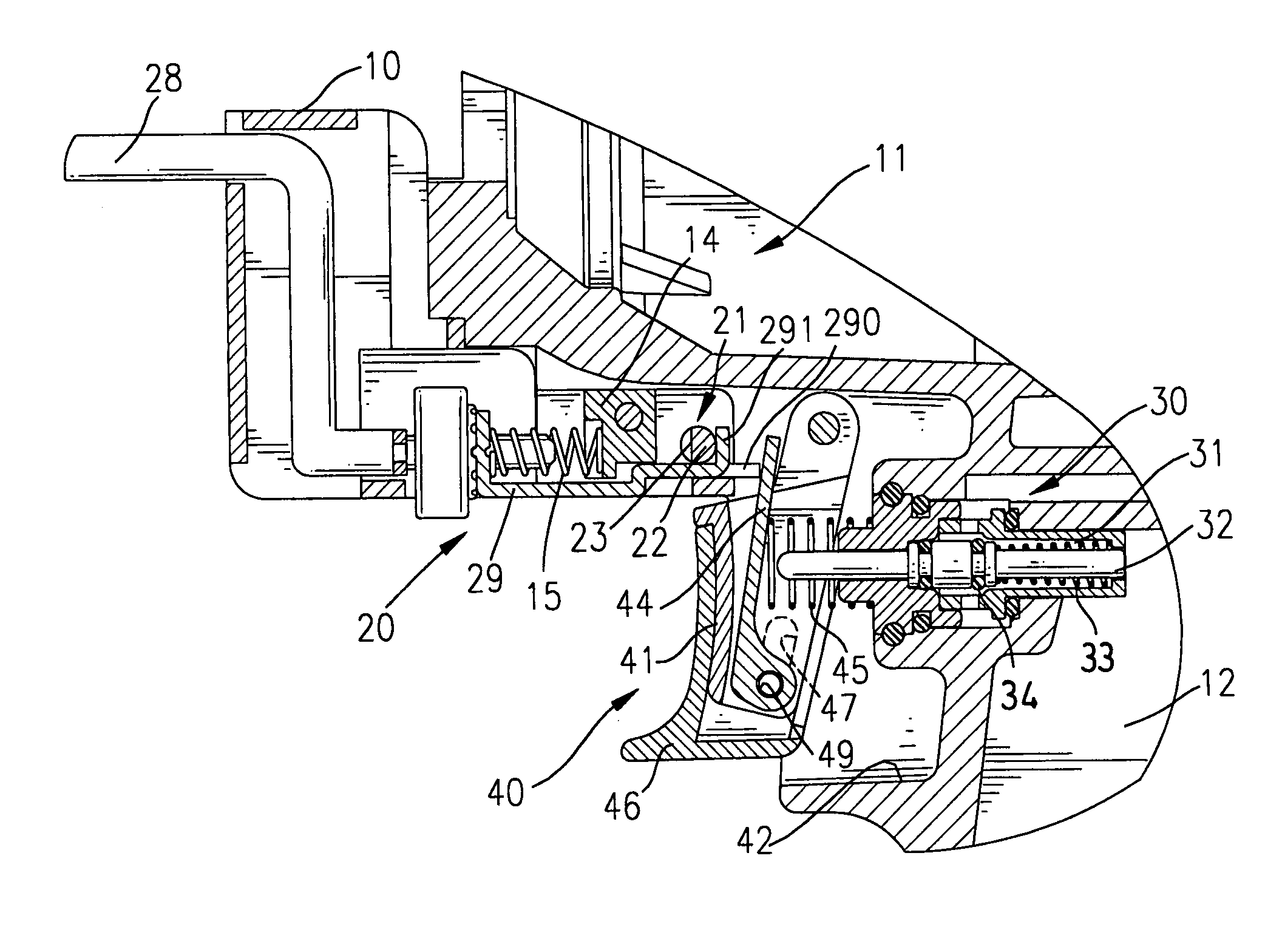
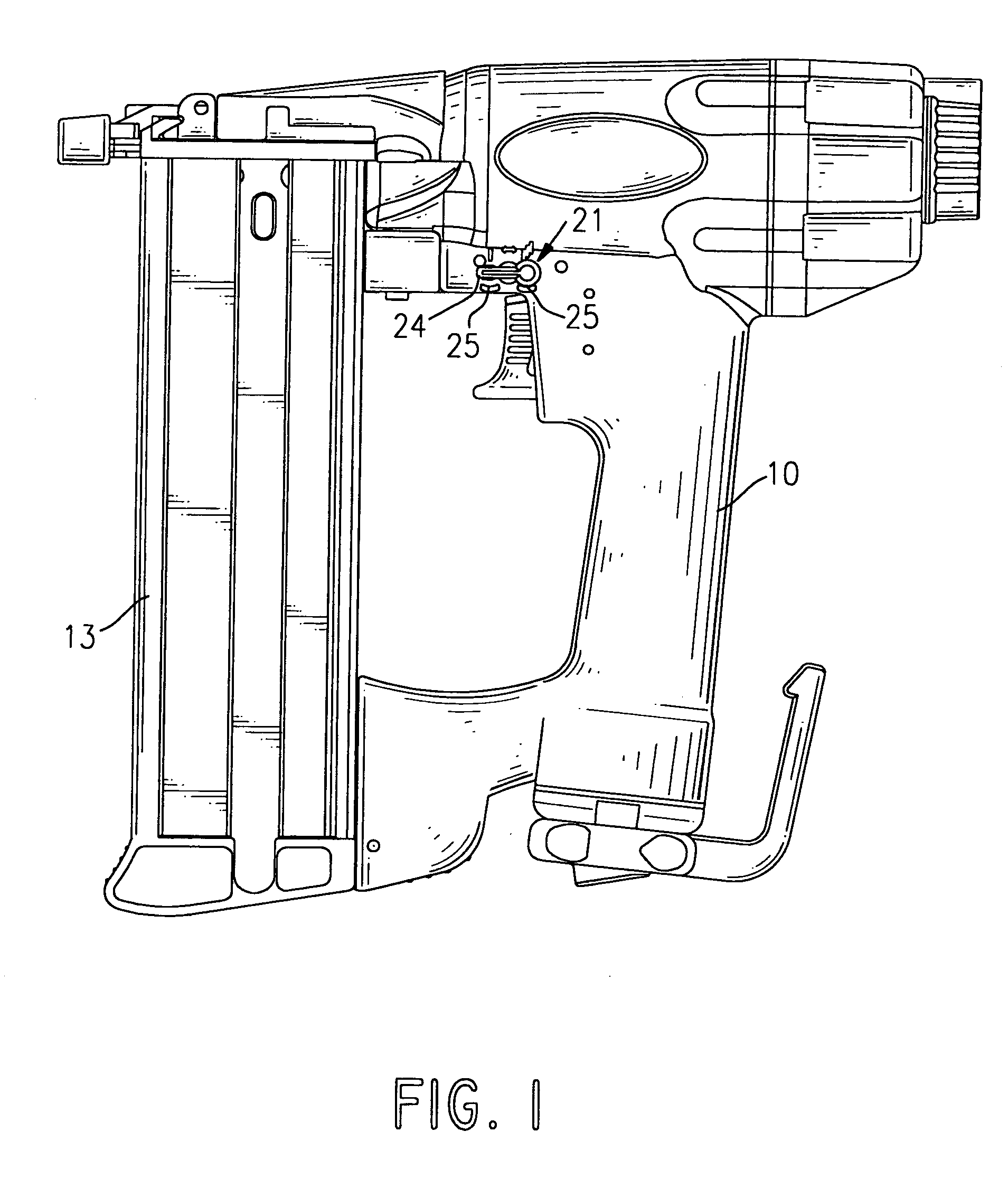
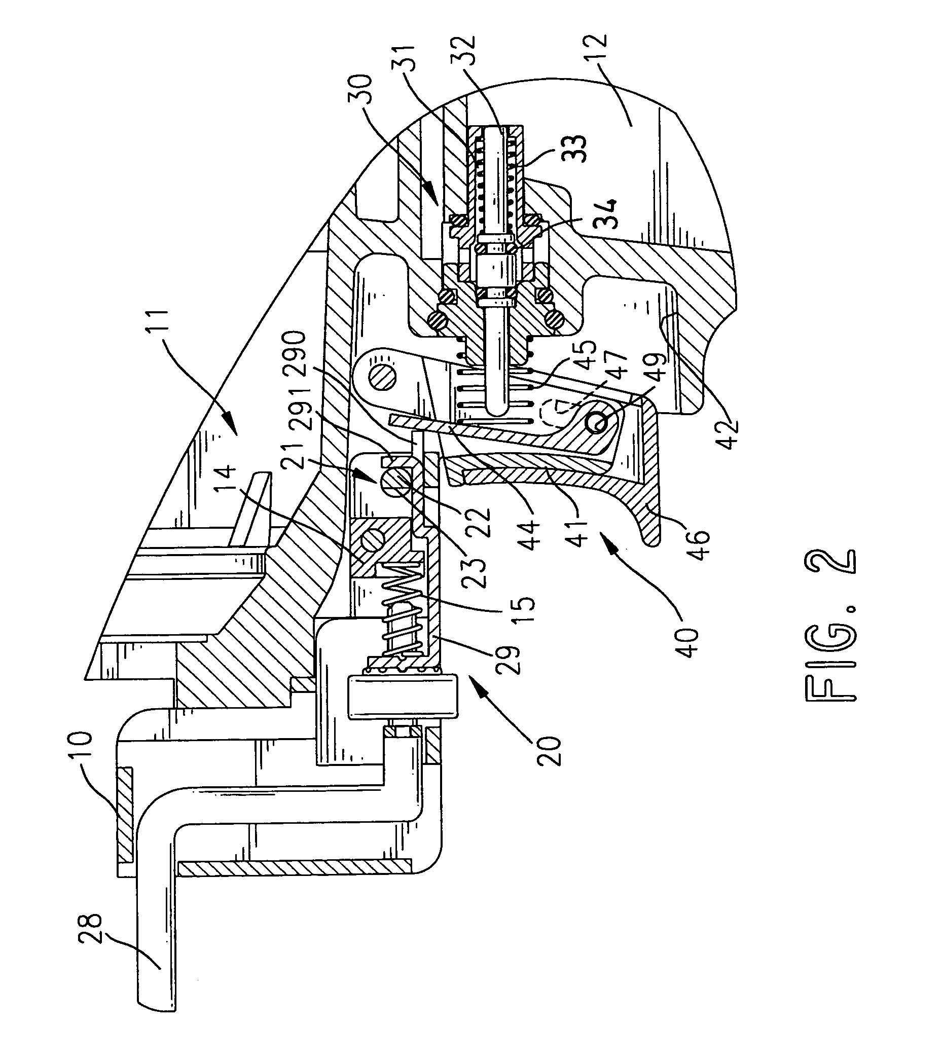
[0018]With reference to FIGS. 1 and 2, a pneumatic nail gun in accordance with the present invention comprises a body (10), a nail magazine (13), an actuating device (30), a trigger assembly (40), a push bar assembly (20) and optionally a switch device (21). The body (10) has a housing and a handle. The housing has a bottom and an inner space, and the handle is formed on the bottom of the housing. The handle has a bottom, an air chamber (12) and a cavity (42). The air chamber (12) is defined in the handle and communicates with the inner space in the housing. A connector is mounted on the bottom of the handle to connect to an air source through a hose, such that high-pressure air can be led into the air chamber (12) through the hose and the connector. The cavity (42) is defined in the handle and has an inner surface.

[0019]The nail magazine (13) is attached to the bottom of the housing and is connected to the handle to provide nails into the body one after one. In addition, the body f...


PUM

PropertyMeasurementUnit
Forceaaaaaaaaaa

Abstract

A pneumatic nail gun has a body, a nail magazine, an actuating device, a trigger assembly and a push bar assembly. The body has a housing, a handle and a nail firing device. The actuating device is mounted between the housing and the handle. The actuating device has a channel, a piston rod, an O-ring and a first spring to provide a restitute force to the piston rod. The trigger assembly is attached to the body and has an inner cap pivotally attached to the body, an outer cap slidably attached outside the inner cap, an actuating lever pivotally attached inside the inner cap and a second spring. Accordingly, the outer cap can be moved to a lock position to keep the nails from being fired unintentionally, and the pneumatic nail gun is safe in use.

Description

BACKGROUND OF THE INVENTION[0001]1. Field of the Invention[0002]The present invention relates to a pneumatic nail gun, and more particularly to a pneumatic nail gun that can improve the safety in use.[0003]2. Description of Related Art[0004]To improve the safety of using a pneumatic nail gun, a push bar is mounted on the pneumatic nail gun, such that the pneumatic nail gun will shoot a nail only when the user pushes the trigger and abuts the push bar against a target simultaneously. In addition, a pneumatic nail gun will be provided with a burst device to shoot the nails continuously until the user releasing the trigger.[0005]However, when the user make the push bar of the conventional pneumatic nail gun abut against a person unintentionally and pushes the trigger simultaneously, the nail will be fired and easily injure the person, especially to a pneumatic nail gun with a burst device.[0006]To overcome the shortcomings, the present invention tends to provide a pneumatic nail gun to...

Claims


Application Information

Patent Timeline
IPC IPC(8): B25C1/00
CPCB25C1/008
Inventor CHEN, RUEY-ZONLO, ERICKU, GEORGE
Owner REXON IND CORP LTD
Why Eureka
Try Eureka