Variable flow fluid tempering valve

a technology of tempering valve and variable flow, which is applied in the direction of tempering control, process and machine control, instruments, etc., can solve the problems of inability to design a tempering valve, inaccurate tempering, and tendency to have a dead zone, and achieve accurate temperature control

Active Publication Date: 2005-08-16
CONBRACO IND
View PDF14 Cites 31 Cited by
  • Summary
  • Abstract
  • Description
  • Claims
  • Application Information

AI Technical Summary

Benefits of technology

[0004]Therefore, it is an object of the invention to provide a tempering valve which provides accurate temperature control at varying flow rates.
[0007]It is another object of the invention to provide a tempering valve which is easily adjusted to a desired temperature.
[0013]A small valve assembly disposed in the first bore includes an outer sleeve having upper and lower ends and being movable between a closed position wherein fluid flow is blocked from the first fluid inlet to the first fluid port, and from the second fluid inlet to the second fluid port, and an open position wherein fluid flow is permitted from the first fluid inlet to the first fluid port, and from the second fluid inlet to the second fluid port; and a first thermal valve disposed in the outer sleeve, the small thermal valve operative to control the relative proportions of fluid flows from the hot and cold water inlets to the bypass passage for maintaining a preselected fluid temperature.

Problems solved by technology

It is difficult to design a tempering valve which accurately maintains a set temperature at widely varying flow rates.
However, when the larger valve does open, it is still only flowing a small percentage of the total flow.
Such a system tends to have a “dead zone” of intermediate flow rates where the tempering is inaccurate.

Method used


Image

  • Variable flow fluid tempering valve
  • Variable flow fluid tempering valve
  • Variable flow fluid tempering valve

Examples


Embodiment Construction

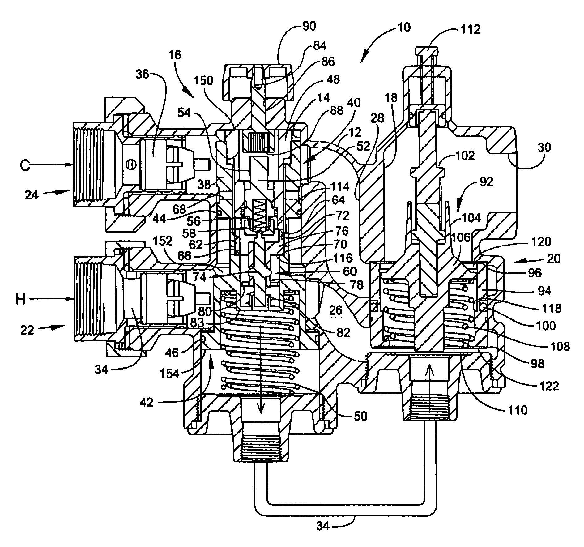
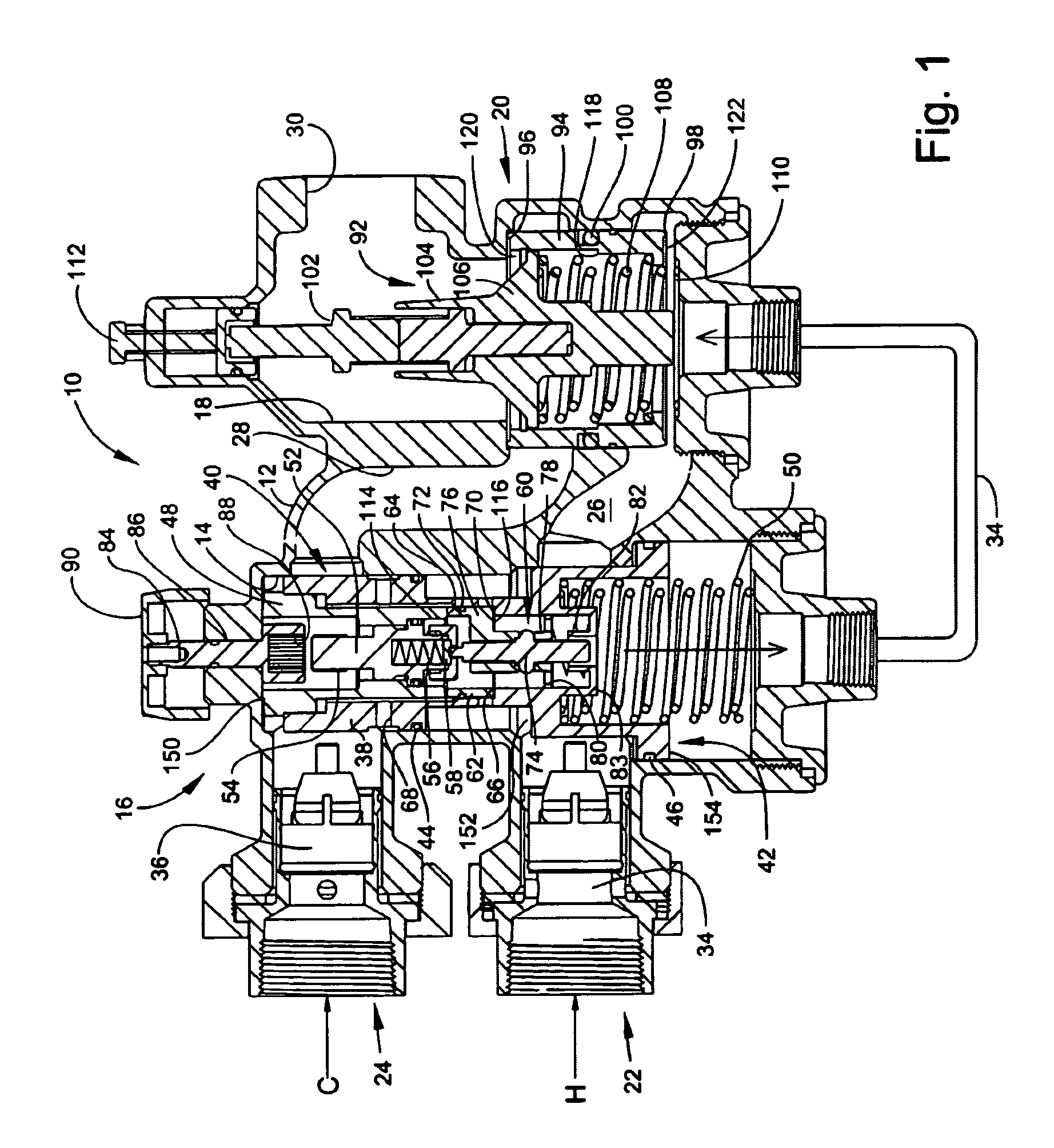
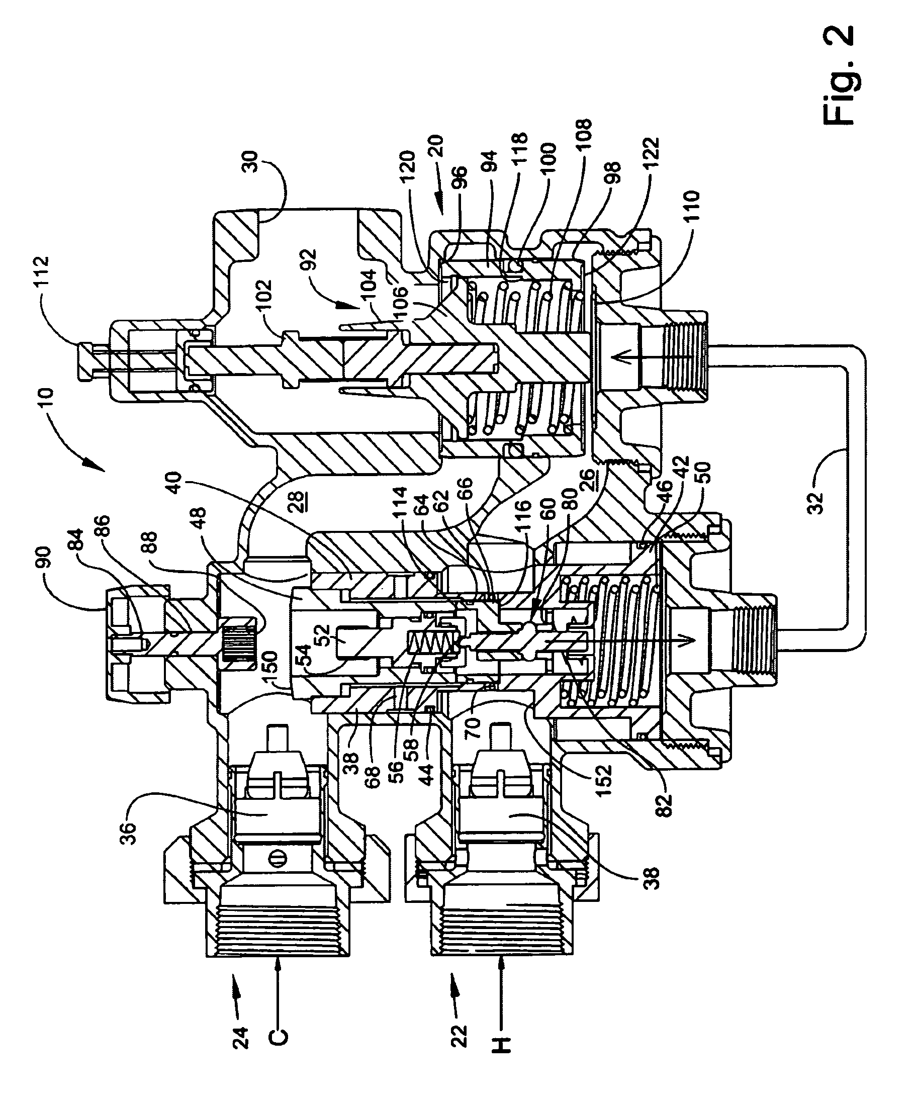
[0033]Referring to the drawings wherein identical reference numerals denote the same elements throughout the various views, FIGS. 1 and 5 illustrate an exemplary tempering valve 10 constructed in accordance with the present invention. It should be noted that the present invention is equally applicable to systems which handle fluids other than water, and therefore the terms “water” and “fluid” are used interchangeably herein when describing the invention. The tempering valve 10 has a housing 12 including a first bore 14 containing a first valve assembly generally referred to as a “small valve assembly”16, and a second bore 18 containing a second valve assembly referred to as a “large valve assembly”20. The housing 12 also includes a hot fluid inlet 22 for receiving fluid from a hot fluid supply H, a cold fluid inlet 24 for receiving fluid from a cold fluid supply C, a hot fluid port 26 extending between the first and second bores 14 and 18, a cold fluid port 28 extending between the ...


PUM


Abstract

A tempering valve is connected to hot and cold water supplies. The tempering valve has first and second thermal valves, each of which mixes hot and cold water flows to produce a tempered flow at a selected temperature. the mixed flow from the first thermal valve bypasses through the second thermal valve. A small valve assembly is responsive to the flow rate therethrough. At low flow rates, direct hot and cold water flow paths to the second thermal valve are blocked. At or above a selected transition flow rate, the small valve assembly opens to permit direct hot and cold water flows from hot and cold water inlets to the second thermal valve. The tempering valve may include a failure protection valve which shuts off all flow in case of a cold water supply failure.

Description

BACKGROUND OF THE INVENTION[0001]This invention relates generally to a fluid tempering valve and more particularly to a tempering valve which accurately controls the temperature of a fluid at both high and low flow rates.[0002]Tempered fluid mixing systems are used in a variety of commercial and industrial applications, for example, in gang showers. A typical system includes a thermostatic mixing valve or tempering valve which automatically blends hot and cold water supply streams to produce a mixed water output stream having a selected temperature. This tempered water is supplied through a common manifold to a plurality of fixtures such as shower heads.[0003]Such tempered water mixing systems must be able to maintain the desired temperature regardless of the flow rate demanded. For example, a system could have a single fixture in use, or more than 20 fixtures could be in use simultaneously. It is difficult to design a tempering valve which accurately maintains a set temperature at ...

Claims


Application Information

Patent Timeline
Patent Type & Authority Patents(United States)
IPC IPC(8): G05D23/13G05D23/01G05D23/12
CPCG05D23/1313
Inventor TAYLOR, GARETH PETERSCHARF, JASON DANIEL
Owner CONBRACO IND
Why Eureka
Try Eureka