
Card connector having an eject lever with a swingable locking member mounted thereto

Active Publication Date: 2005-08-16
JAPAN AVIATION ELECTRONICS IND LTD
View PDF19 Cites 12 Cited by
  • Summary
  • Abstract
  • Description
  • Claims
  • Application Information

AI Technical Summary

Benefits of technology

[0007]It is therefore an object of the present invention to provide a card connector with a locking mechanism high in durability even if the eject lever is reduced in size.

Problems solved by technology

However, such an eject lever is disadvantageous because it is not rigid enough to support or withstand a moment during deformation of the locking member.
In particular, in the structure in which the locking member is press-fitted to and held by the eject lever in a cantilevered fashion as disclosed in JP-A 2001-326028, the mechanical strength is insufficient in practical use.

Method used


Image

  • Card connector having an eject lever with a swingable locking member mounted thereto
  • Card connector having an eject lever with a swingable locking member mounted thereto
  • Card connector having an eject lever with a swingable locking member mounted thereto

Examples


Embodiment Construction

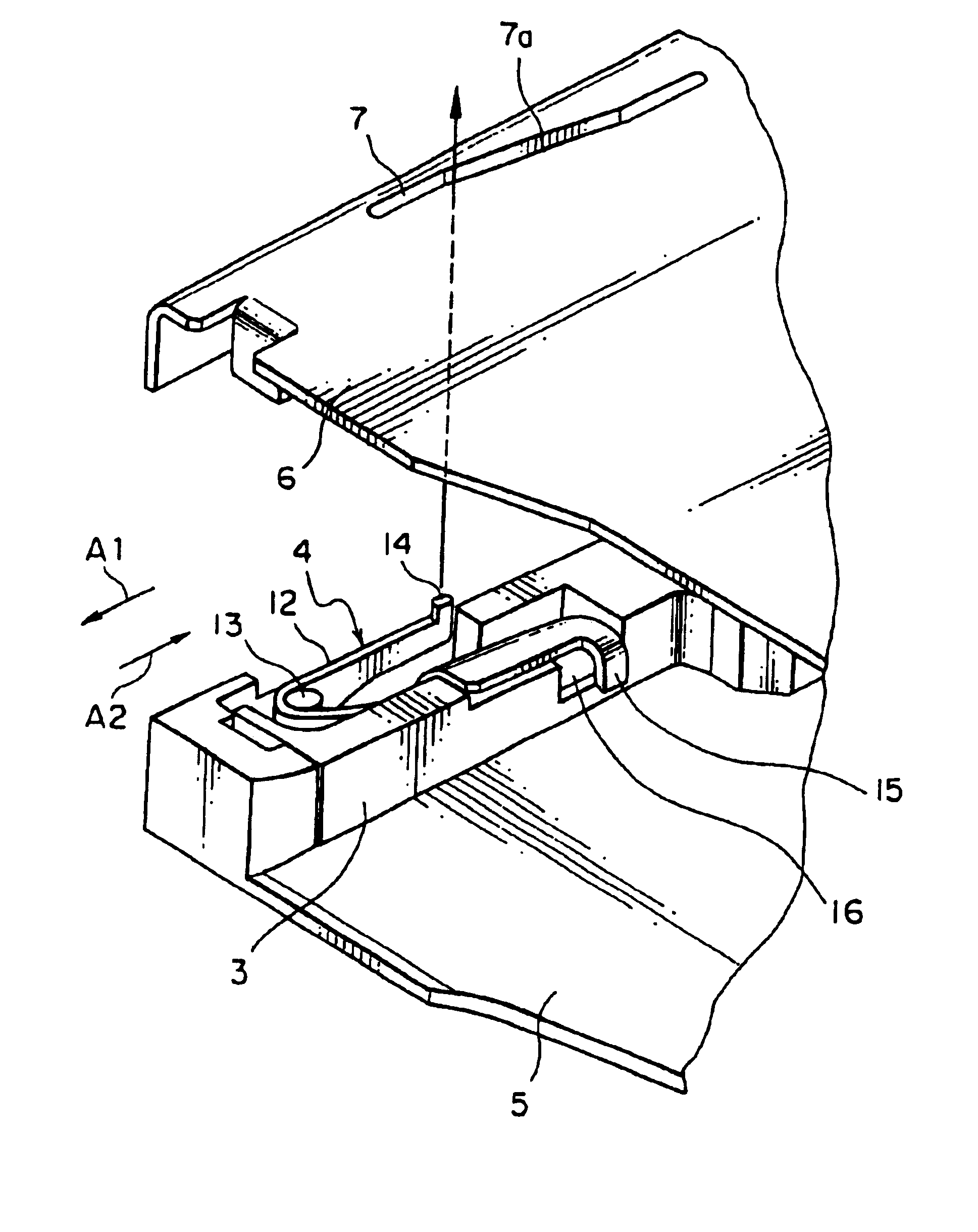
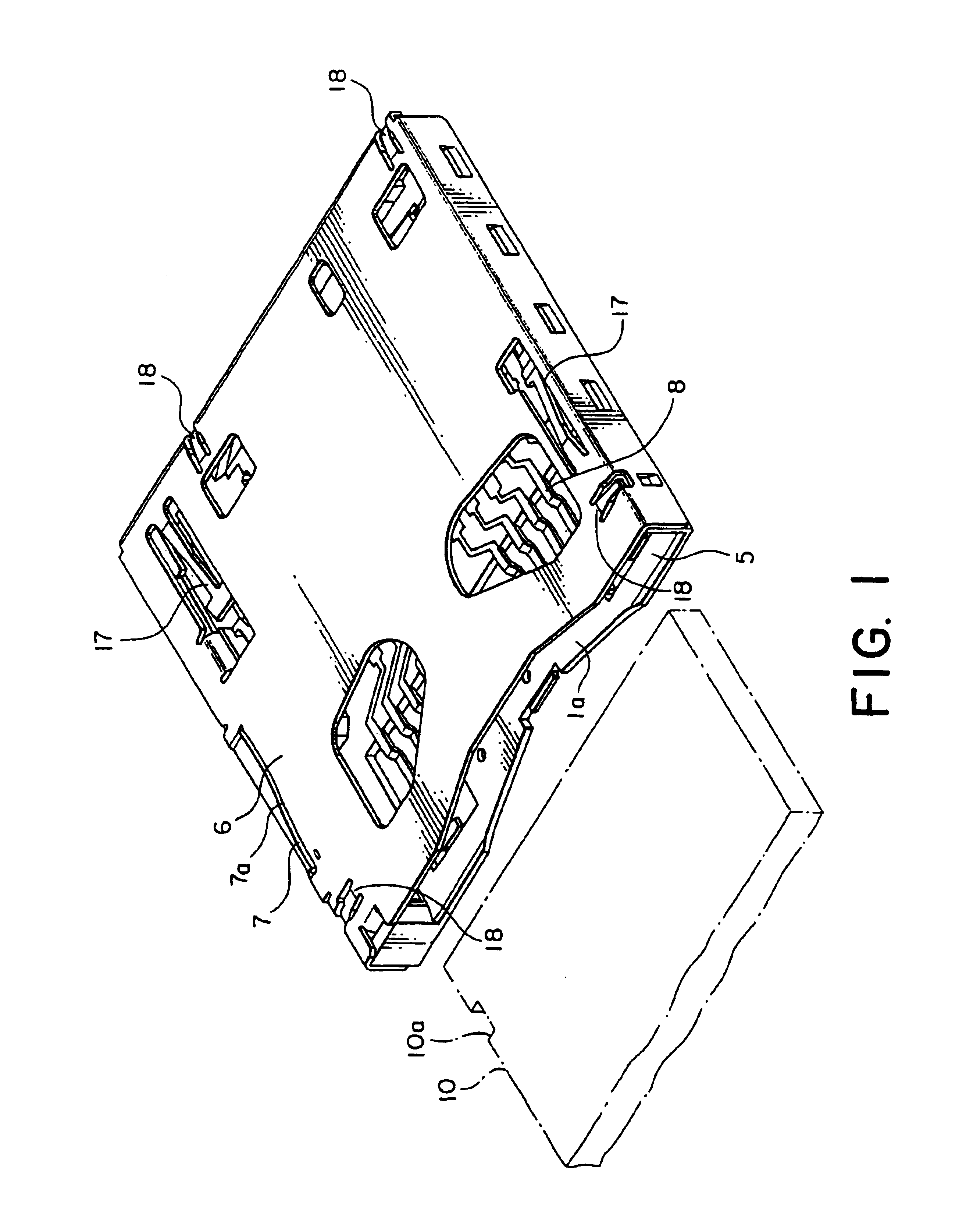
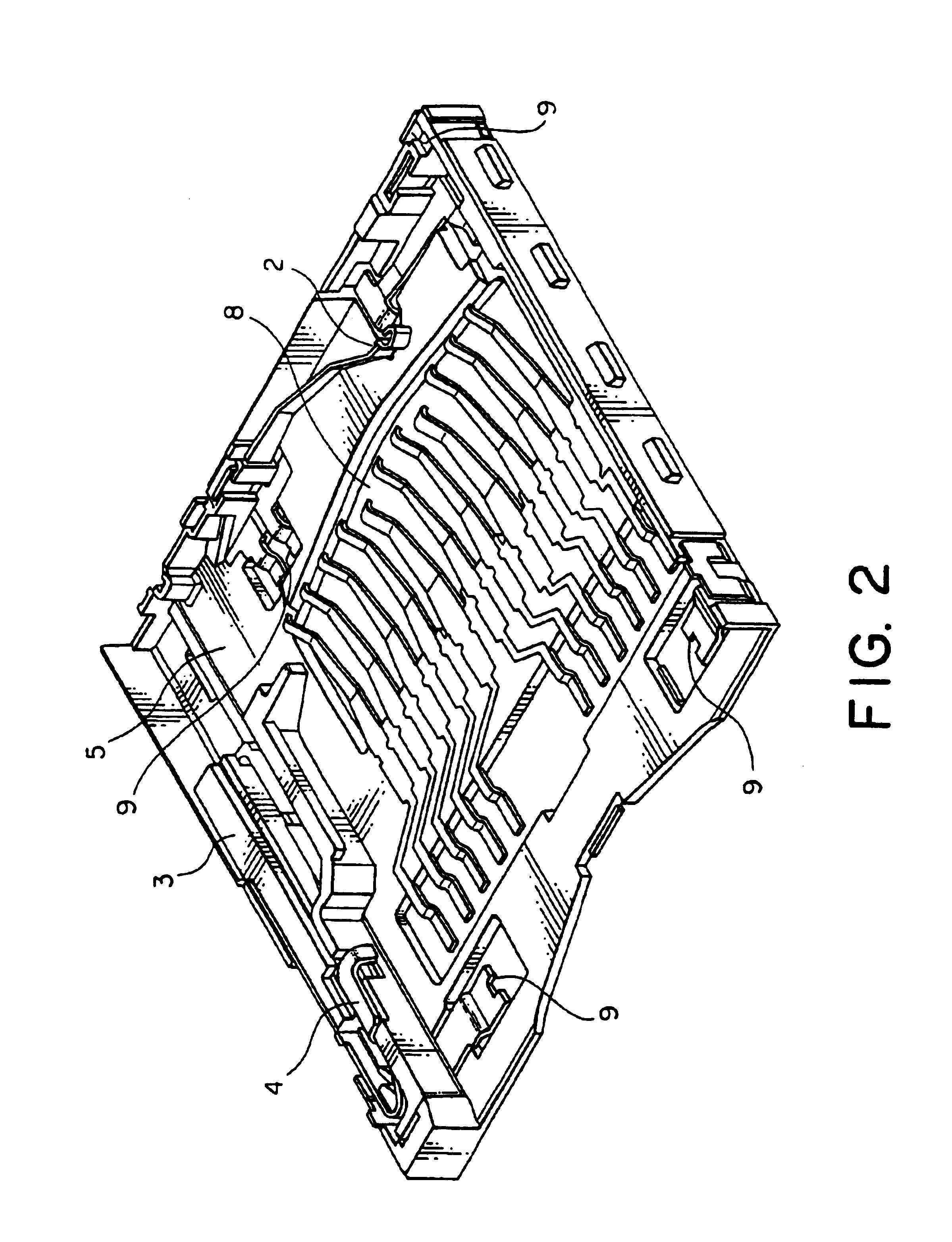
[0017]Referring to FIGS. 1 through 3, the card connector is to be connected to a card 10, such as an IC card and a communication card, and comprises a case or a housing 1 defining a card receiving area 1a for receiving the card 10, a detection switch 2 disposed at one end of the housing 1 to detect insertion of the card 10, an eject lever 3 held by the housing 1 to be reciprocally slidable in first and second directions A1 and A2 and adapted to eject the card 10 from the card receiving area 1a, and a locking member 3 swingably held by the eject lever 3.

[0018]The housing 1 has an insulating base 5 and a cover 6 fixed to the base 5. Between the base 5 and the cover 6, the card receiving area 1a is defined. The eject lever 3 is held by the base 5. The cover 6 is provided with a cam portion 7. The cam portion 7 has an inclined intermediate part 7a inclined with respect to the first and the second directions A1 and A2.

[0019]The base 5 is provided with a plurality of conductive contacts 8...


PUM


Abstract

A housing (1) is provided with an eject lever (3) for ejecting a card (10). The eject lever holds a locking member (4) to be swingable around a support shaft (13). The housing is provided with a cam portion (7). The locking member is provided with a cam follower portion (14) to be engaged with the cam portion and a locking portion (15) for locking the card to inhibit the release of the card. When the eject lever is made to perform sliding movement, the cam portion and the cam follower portion cooperate to swing the locking member so that the card is locked and unlocked by the locking portion.

Description

[0001]The invention claims priority to prior Japanese application JP 2002-377759, the disclosure of which is incorporated herein by reference.BACKGROUND OF THE INVENTION[0002]This invention relates to a card connector to be connected to a card, such as an IC card and a communication card, and, in particular, to a card connector having a locking mechanism for preventing accidental release of a card.[0003]Generally, a card connector has an eject mechanism for ejecting a card. For example, an eject mechanism called a W-PUSH type or a push—push type is known. The eject mechanism of this type has an eject lever to be moved within the connector together with the card inserted in the connector.[0004]A structure in which the eject lever holds a locking member as a part of a locking mechanism for preventing accidental escape of the card from the card connector has been proposed, for example in Japanese Patent Application Publication No. 2001-326028. In this structure, the locking member is p...

Claims


Application Information

Patent Timeline
IPC IPC(8): G06K13/08G06K13/02H01R13/633H01R13/635H01R13/703H01R13/70G06K17/00H01R13/629H01R13/639
CPCG06K13/08G06K13/0806G06K13/0825H01R13/635H01R13/7035
Inventor KODERA, MASAFUMIMOTOJIMA, JOENATORI, AKIRASUZUKI, KEIICHIRO
Owner JAPAN AVIATION ELECTRONICS IND LTD
Learn More