Connector for memory cards

a technology for connecting cables and memory cards, applied in the direction of coupling devices, coupling contact members, two-part coupling devices, etc., can solve the problems of affecting the operation of portable devices, increasing the volume of information equipment, and plurality of connectors, so as to avoid damage to the housing and reliably retain the terminals in position

Inactive Publication Date: 2005-08-16
HON HAI PRECISION IND CO LTD
View PDF10 Cites 23 Cited by
  • Summary
  • Abstract
  • Description
  • Claims
  • Application Information

AI Technical Summary

Benefits of technology

[0009]Another object of the present invention is to provide a compact connector having improved side-to-side alignment terminals for precisely engaging with the contact pads of the cards and precisely soldering to a printed circuit board.
[0011]Because the connector for memory cards employs the insert which is capable of receiving two or more types of terminals without defining too many terminal-receiving passageways in the housing and without affecting the intensity of the housing, thereby avoiding damage of the housing and reliably retaining the terminals in position and ensuring interconnection between the terminals and the cards.

Problems solved by technology

As time goes by, the information apparatuses and hence their boards have been rapidly miniaturized, so that areas occupied by the boards have been limited.
What is worse, a plurality of connectors increase the volume of the information apparatuses, which are incompatible with the miniaturization and in no way suitable for portable apparatus.
Defining too many passageways is inclined to damnify the plane of the lower base.
More, the contact portions of the terminals disposed at the conduction part of the lower base is hardly possible coplanar, so as to result in incomplete interconnection between the terminals of the connector and the contact pads of the memory cards, and in turn, result in incomplete or deficient connection to external equipment.
These solder portions tend to be interfered with each other, thus rendering unsatisfied layout thereof.

Method used


Image

  • Connector for memory cards
  • Connector for memory cards
  • Connector for memory cards

Examples


Embodiment Construction

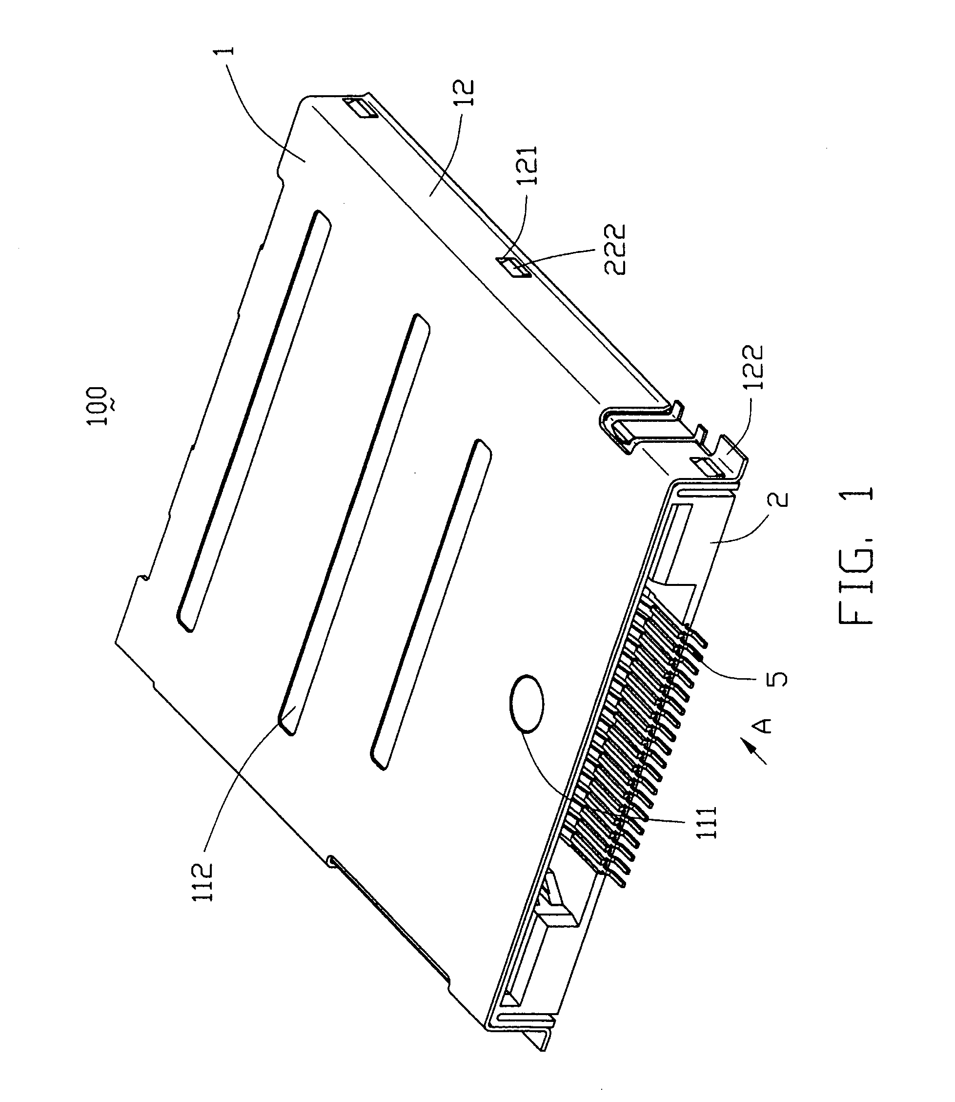
[0024]Referring to FIG. 1, in the present embodiment, a connector 100 is possible for being alternatively inserted with a Smart Media (SM) card, a Memory Stick (MS) card, a Secure Digital (SD) or a Multi Media (MMC) card and a xD-picture card.

[0025]Certain terminology may be used in the following description for convenience only and is not considered to be limiting. The words “upper”, “lower”, “front” and “rear”, “forwardly”, “rearwardly”, “upwardly” and “downwardly” make reference to arrow A (shown in FIG. 1) hereinafter, that is insert direction of the memory cards.

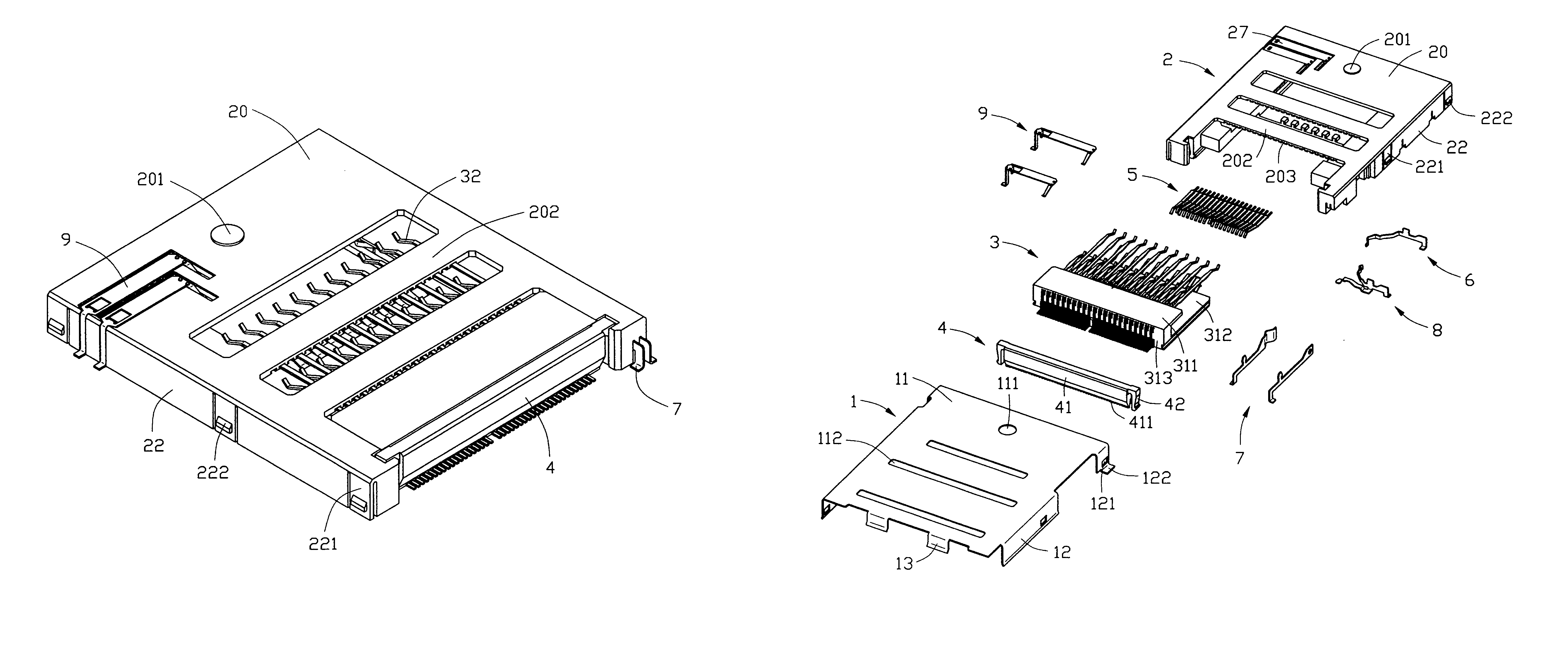
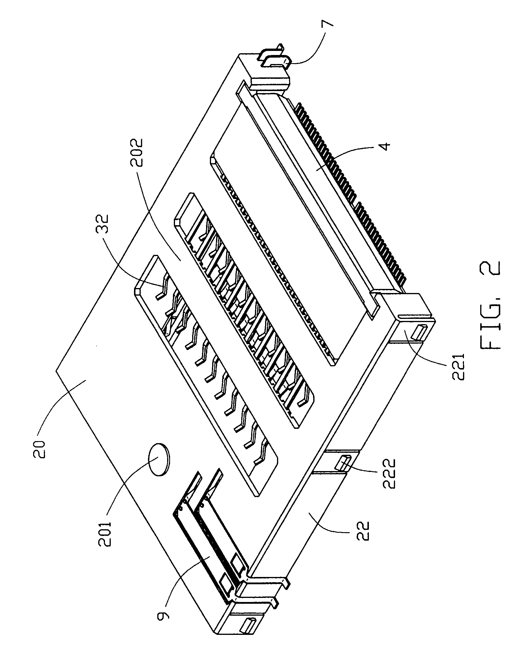
[0026]Referring to the drawings in greater detail, and first to FIGS. 1–5, a connector 100 according to the present invention comprises a shield 1, an insulative housing 2 enclosed by the shield 1, a terminal module insert 3 embedded within the housing 2 and a positioning member 4 detachably assembled in the housing 2 for securing the insert 3 in the housing 2.

[0027]The shield 1 is of a substantially rectangular-shaped ...


PUM


Abstract

A connector (100) for receiving at least two types of memory cards differing in outer shapes and contact pad positions includes an insulative housing (1) and a terminal module insert (3) fixedly assembled to the housing. The insert includes an insulative casing (31) having an upper plate (311), a lower plate (312) and an upright plate (313). The casing defines a plurality of outlets (316) and forms a plurality of partitions (317) at the upright plate. The terminals forwardly project for electrically engaging with contact pads of the at least two types of cards and rearwardly project beyond the outlets to be fixed between corresponding pairs of partitions for being soldered to the printed circuit board.

Description

CROSS-REGERENCE TO RELATED APPLICATIONS[0001]This application is related to co-pending U.S. patent applications entitled “CONNECTOR FOR MEMORY CARDS”, entitled “MEMORY CARD CONNECTOR”, and entitled “MEMORY CARD CONNECTOR”, all of which are invented by the same inventor and assigned to the common assignee as the present invention.BACKGROUND OF THE INVENTION[0002]1. Field of the Invention[0003]The present invention relates to connectors and more particularly, to an electrical connector for receiving two or more cards differing in outer shapes and contact pad positions.[0004]2. Description of the Related Art[0005]Memory cards different in thickness as media for information have been mounted on and connected to information apparatuses through a respective connector exclusive to one particular type of the memory card among the number of the memory cards for reading information stored in the card and storing information into the card. As time goes by, the information apparatuses and hence...

Claims


Application Information

Patent Timeline
Patent Type & Authority Patents(United States)
IPC IPC(8): H01R27/00H01R13/02H01R13/35
CPCH01R27/00H01R13/35
Inventor FAN, CHIA HAO
Owner HON HAI PRECISION IND CO LTD
Why Eureka
Try Eureka