Brushless electro-mechanical device

Inactive Publication Date: 2005-08-16
HIPPERT MICHAEL
View PDF34 Cites 35 Cited by
  • Summary
  • Abstract
  • Description
  • Claims
  • Application Information

AI Technical Summary

Benefits of technology

[0008]The machine includes at least one motor drive electronics module for energizing the toroidal electromagnetic members with current according to a predetermined sequence. The sequence is triggered by Hall effect sensors placed adjacent the electromagnetic members along the arc. The Hall effect sensors sense changes in the magnetic field and provides trigger signals to the electronics

Problems solved by technology

Electric motors employing brushes are characterized by low efficiency and require elaborate starter mechanisms.
A problem with the motor of the '307 patent is that the permanent magnets are spaced too far apart about the periphe

Method used


Image

  • Brushless electro-mechanical device
  • Brushless electro-mechanical device
  • Brushless electro-mechanical device

Examples


Embodiment Construction

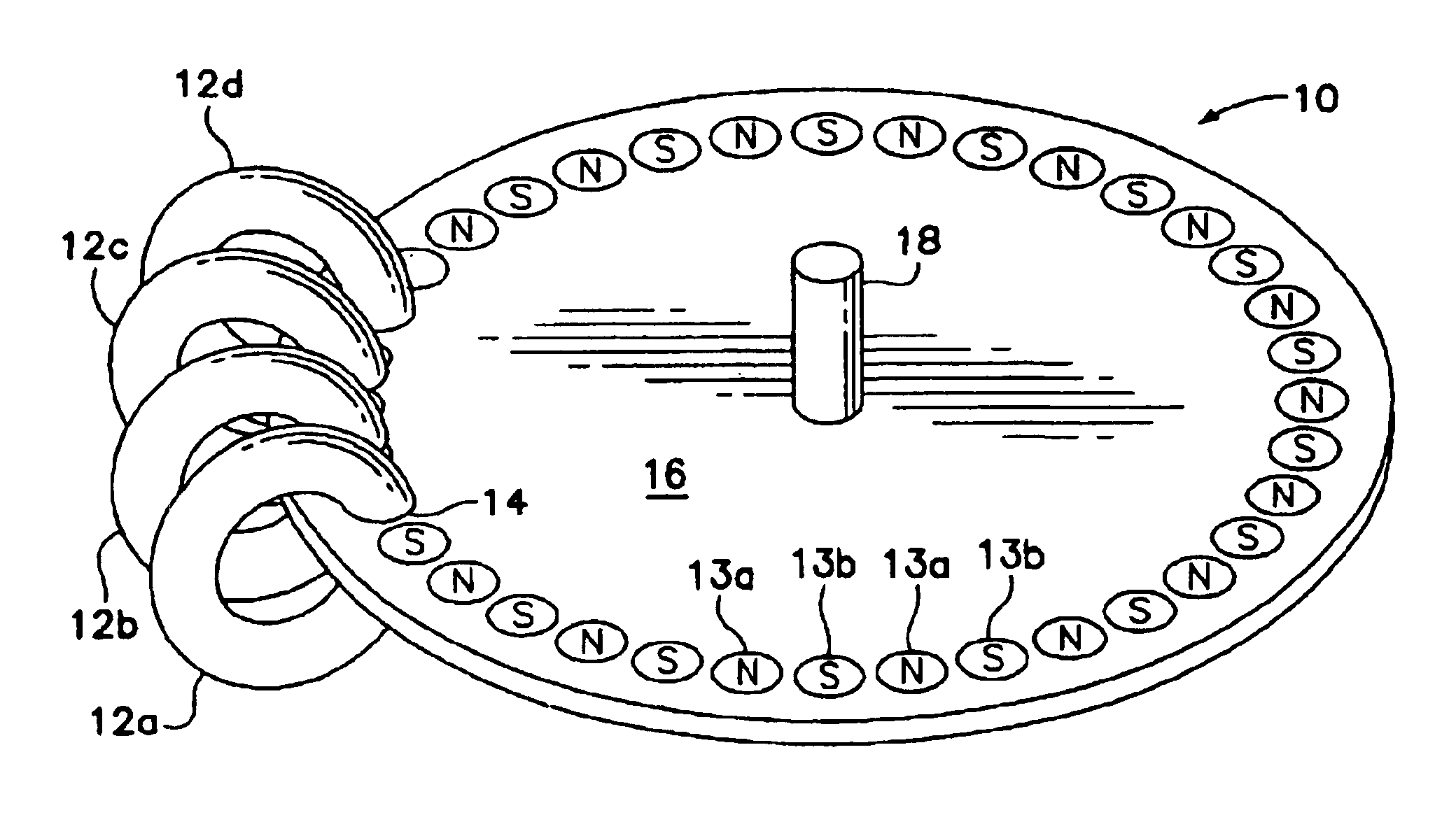
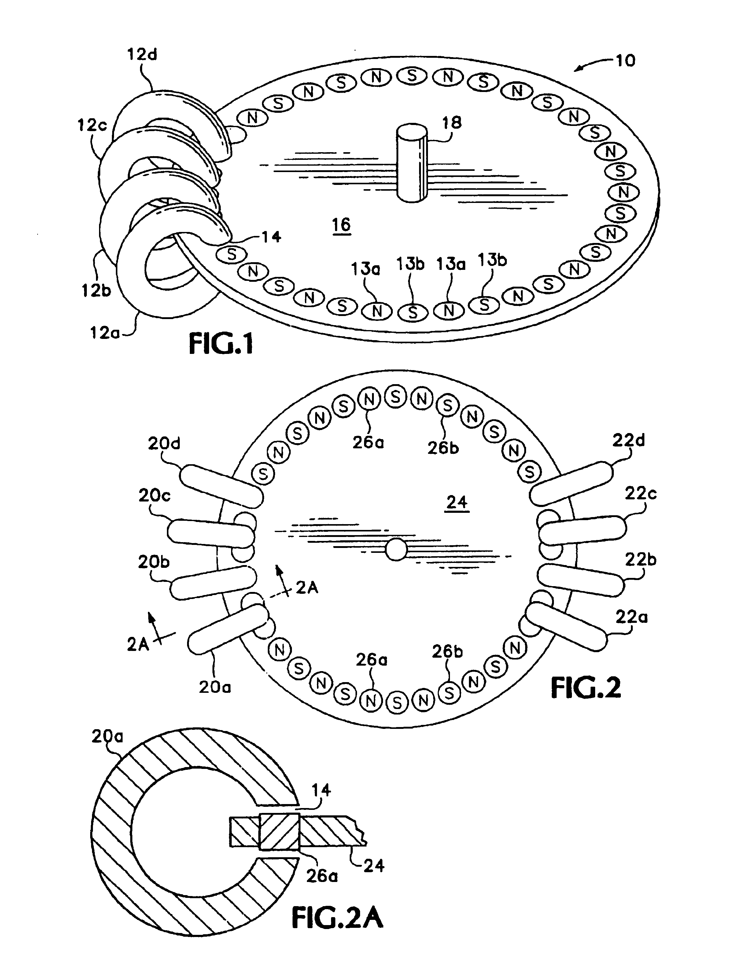
[0024]An electromechanical machine 10 is shown schematically in FIG. 1. The machine 10 includes a plurality of toroidally shaped electromagnets 12. There are four such electromagnets 12a, 12b, 12c and 12d. The electromagnets 12a-d are arranged along an arc having a predetermined length. Each of the electromagnets is toroidally shaped and each has a gap 14 (refer to FIG. 2A). The gaps 14 are aligned which permits the outer edge of a wheel or disk 16 to pass through them. The disk 16 has an output shaft 18 which may be coupled to any suitable device such as a fan or a tub for a washing machine (not shown). The output shaft could also be coupled to some source of rotational energy such as a drive shaft. In this configuration, the motor is initially used as a starter motor and then switches into a generator or alternator mode.

[0025]The disk includes a plurality of permanent magnet members 13a, 13b which are arranged in alternate north-south polarity. The magnets 13a, b are sized and spa...


PUM


Abstract

An electromotive machine having a stator element and a rotor element, the stator element including at least one set of N preferably toroidally shaped electromagnetic members, the electromagnetic members arranged along an arc a predetermined distance apart defining a stator arc length. Each of the members has a slot, and the rotor element includes a disc adapted to pass through the slots. The disc contains a plurality of permanent magnet members spaced side by side about a periphery thereof and arranged so as to have alternating north-south polarities. These permanent magnet members are sized and spaced such that within the stator arc length the ratio of stator members to permanent magnet members is N to N+1, where N is the number of electrical excitation phases applied to the electromagnets. The electromagnetic members are energized to create high torque and smooth operation.

Description

[0001]This application is a continuation in part of U.S. application Ser. No. 10 / 417,713 filed Apr. 16, 2003.BACKGROUND OF THE INVENTION[0002]The following invention relates to a brushless electromechanical machine for converting electrical energy into mechanical motion and vice-versa. More specifically, the invention relates to an electric motor / generator having self-starting capabilities, high torque and increased efficiency.[0003]Electric motors employing brushes are characterized by low efficiency and require elaborate starter mechanisms. Recently, a type of brushless motor has been developed which employs an electromagnet having a stator comprised of a plurality of toroidal pole pieces. The pole pieces each have a narrow gap to permit the passage of a disk shaped rotor. The rotor includes a plurality of permanent magnet members spaced about the periphery of the disk. As the permanent magnet members pass through the gap in the stator poles, the magnetic circuit is completed. Wit...

Claims


Application Information

Patent Timeline
IPC IPC(8): H02K1/27H02K3/28H02K41/03H02K21/16H02K1/14H02P25/02
CPCH02K1/2793H02K3/28H02K21/16H02K41/03H02P25/021H02K1/141H02P25/024H02K1/2798
Inventor BALES, JOHN E.LONG, TOMSAUNDERS, J. LYNNSABRI, MOHAMED
Owner HIPPERT MICHAEL
Why Eureka
Try Eureka