Insert earphone

a technology of inserting earphones and earphones, which is applied in the direction of earpiece/earphone attachments, deaf-aid sets, ear supported sets, etc., to achieve the effect of preventing sound leakage and improving comfort in wearing

Inactive Publication Date: 2005-08-16
STAR MICRONICS
View PDF1 Cites 30 Cited by
  • Summary
  • Abstract
  • Description
  • Claims
  • Application Information

AI Technical Summary

Benefits of technology

[0013]An object of the present invention is to provide an insert earphone which effectively prevents a sound leakage and improves comfort in wearing the insert earphone.
[0014]The insert earphone of the present invention achieves the object by providing a first annular flange portion of an improved structure.
[0023]The insert earphone of the present invention has the following advantages.
[0025]Therefore, the first annular flange portion is in closely and reliably contact with the wall face of the external auditory meatus, effectively preventing a sound leakage. The outer circumference neighborhood of the first annular flange portion is in contact with the wall face of the external auditory meatus at substantially uniform pressing force over the entire periphery. It assures sufficient contacting function even if the pressing force is set at a small value. Accordingly, the first annular flange portion does not partially strongly press the wall face of the external auditory meatus, thereby increasing comfort while wearing the ear chip.
[0026]According to the insert earphone of the present invention, a sound leakage is effectively prevented and comfort in wearing the ear chip is increased.
[0027]Since the first annular flange portion is in closely contact with the wall face of the external auditory meatus to successfully prevent a sound leakage, the second annular flange portion can be dedicated to the supporting function of the insert earphone Assigning different functions to the separate flange portions maximizes acoustic performance of the insert earphone.

Problems solved by technology

Such conventional insert earphone with a dual flange structure, however, has a disadvantage in that every part of periphery of the first annular flange portion 114B unevenly contacts with the wall face 2a since the external auditory meatus 2 extends in not a simple cylindrical shape but a complex curved shape.

Method used


Image

  • Insert earphone
  • Insert earphone
  • Insert earphone

Examples


Embodiment Construction

[0034]The present invention will be described below with reference to the accompanying drawings.

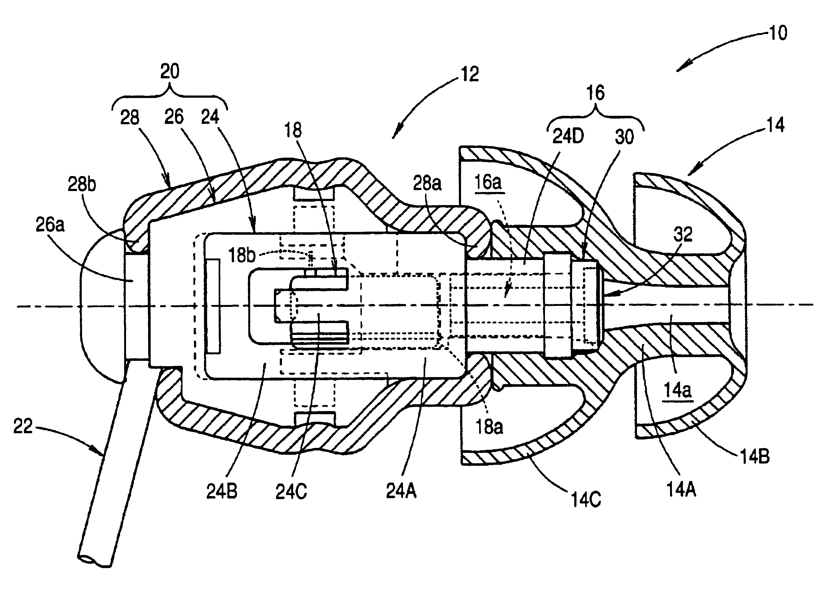
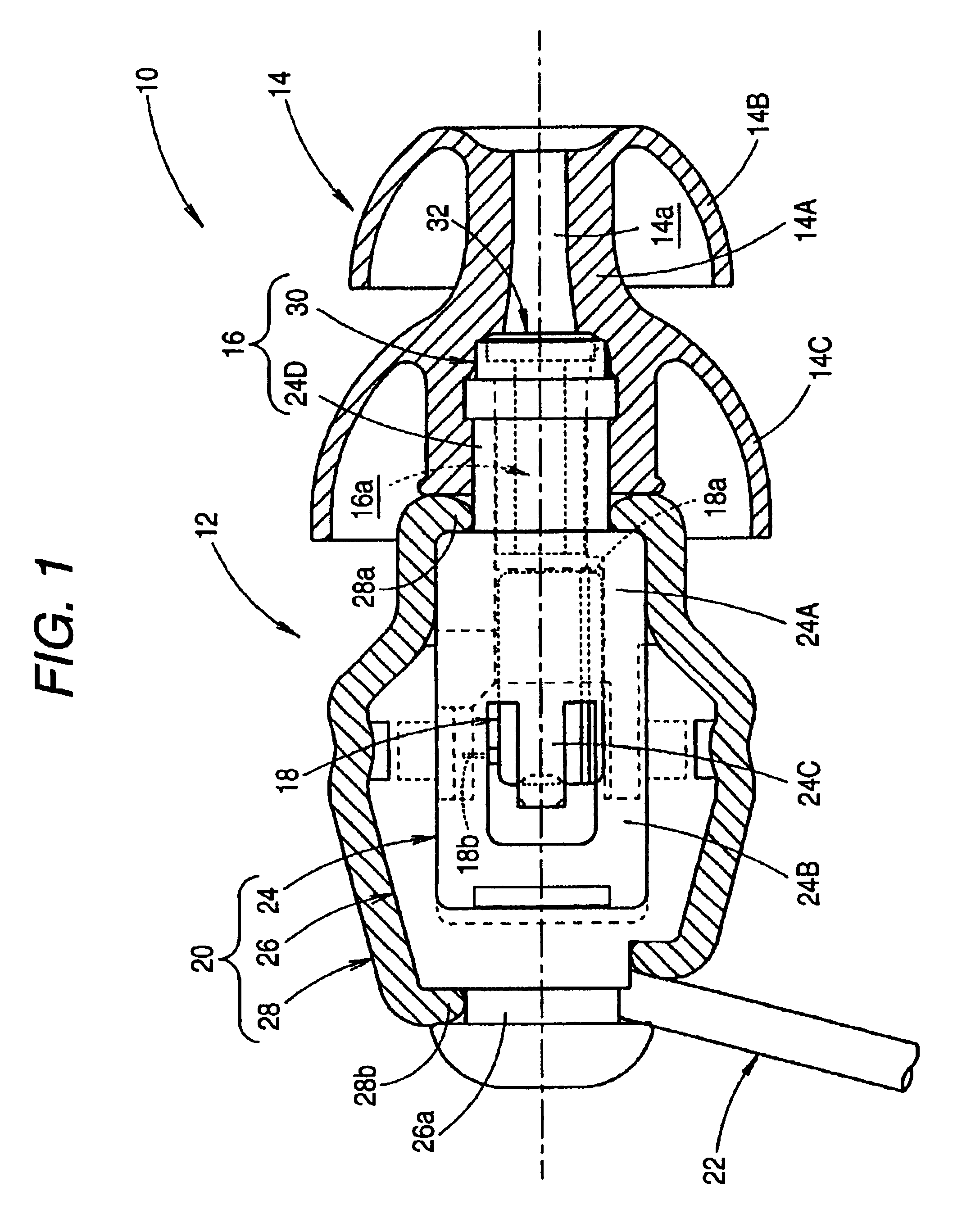
[0035]FIG. 1 is a partially sectional side view of an insert earphone 10 of the present invention.

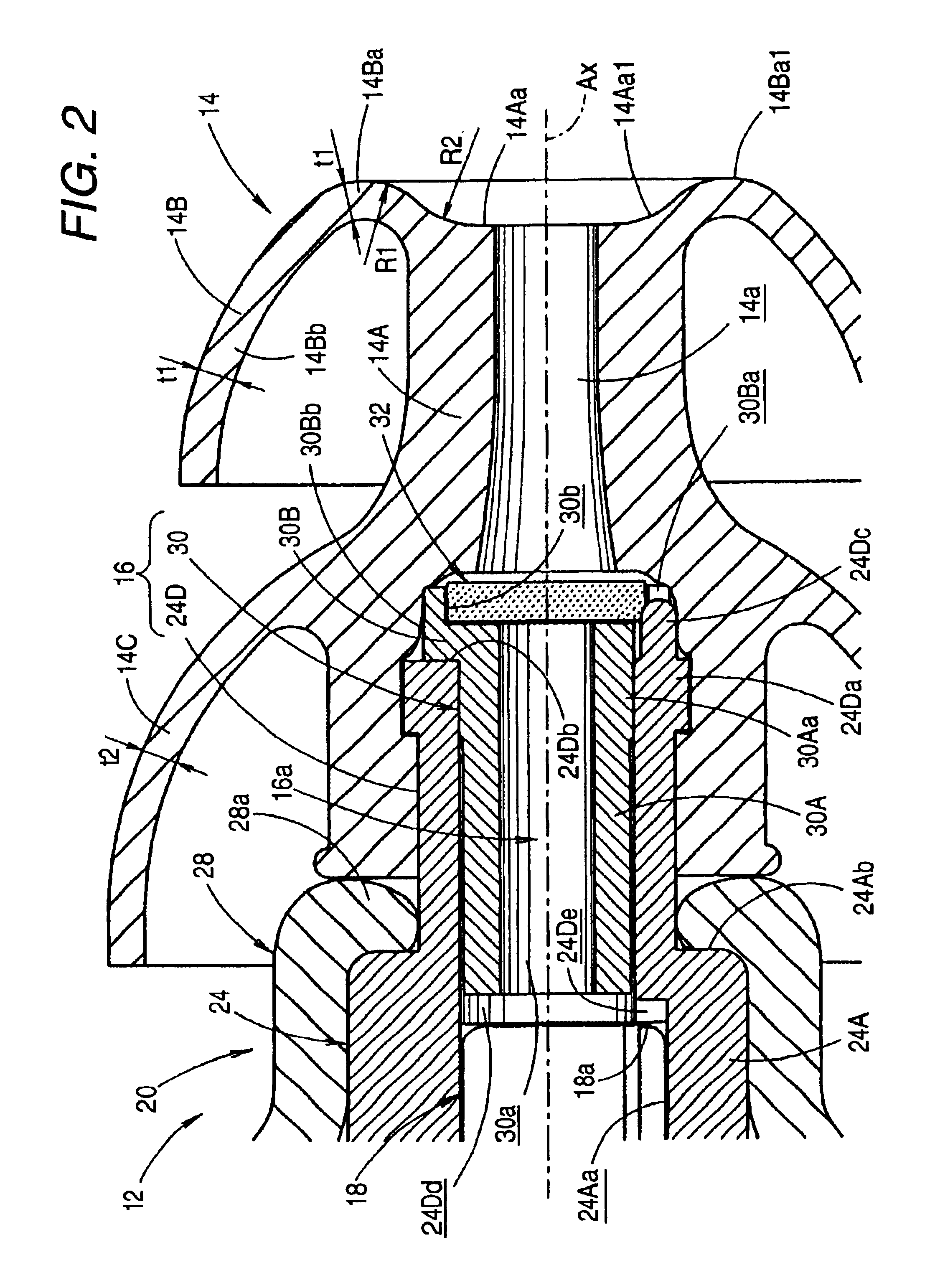
[0036]FIG. 2 is a partial side sectional view of the insert earphone 10.

[0037]As shown in these drawings, the insert earphone 10 comprises a receiver unit 12 and an ear chip 14. The receiver unit 12 has a sound passage tube 16 on a front end portion thereof (right end portion in FIG. 1). The ear chip 14 is fitted to the sound passage tube 16. The insert earphone 10 is used in state where the ear chip 14 is inserted into an external auditory meatus.

[0038]The receiver unit 12 comprises a receiver main body 18, a housing 20 accommodating the receiver main body 18, and a cord 22 connected to the receiver main body 18.

[0039]The receiver main body 18 comprises an electromagnetic receiver of a balance armature type which has substantially a rectangular parallelepiped outer shape. The receiver main b...


PUM


Abstract

An insert earphone which prevents a sound leakage and improves wearing comfort. An ear chip has a barrel portion and first and second annular flange portions having the shape of a parabola spreading from the top toward the middle and from the middle toward the base of the barrel portion respectively. The first annular flange portion has a smaller outer diameter than the second annular flange portion. The first annular flange portion has almost even thickness from the inner circumference to the outer circumference, and has the inner circumference neighborhood substantially formed in the shape of a sliced doughnut.

Description

BACKGROUND OF THE INVENTION[0001]1. Field of the Invention[0002]The present invention relates to an insert earphone, particularly to a structure of an ear chip thereof.[0003]2. Description of the Related Art[0004]An insert earphone conventionally comprises a receiver unit having a sound passage tube, and an ear chip attached to the receiver unit. The insert earphone is used in state where the ear chip is inserted into an external auditory meatus.[0005]The ear chip of the insert earphone comprises a barrel portion and an annular flange portion. The barrel portion defines a sound passage which communicates to a sound passage of the sound passage tube of the receiver unit. The annular flange portion has the shape of a parabola spreading from the top end of the barrel portion toward the base end thereof. When the ear chip is inserted into the external auditory meatus, the insert earphone is supported by the annular flange portion. The annular flange portion abuts on a wall face of the e...

Claims


Application Information

Patent Timeline
Patent Type & Authority Patents(United States)
IPC IPC(8): H04R1/10
CPCH04R1/1016
Inventor FUSHIMI, ISAO
Owner STAR MICRONICS
Why Eureka
Try Eureka