
Multifiber connector, installation tool and associated methods of validating optical fiber continuity

a multi-fiber connector and optical fiber technology, applied in the field of connecting optical fibers, can solve the problems of deactivation of the cam mechanism, optical field fiber and optical fiber stub, etc., and achieve the effect of facilitating the rapid repositioning of optical field fibers

Inactive Publication Date: 2005-08-16
CORNING OPTICAL COMM LLC
View PDF6 Cites 73 Cited by
  • Summary
  • Abstract
  • Description
  • Claims
  • Application Information

AI Technical Summary

Benefits of technology

The present invention provides methods for validating the continuity of optical fibers and fiber optic connectors in a simple and efficient way. The methods involve introducing light into the optical fibers and monitoring the glow that emanates from the end of the fibers or the optical fiber stubs. The glow indicates the presence of a connection between the fibers and the absence of any unacceptable discontinuity. The methods can be performed with a simple tool and do not require the replacement of expensive fiber optic connectors. The invention also provides a multifiber connector with a cam mechanism for securely positioning the optical field fibers and optical fiber stubs. The connector is designed to facilitate the evaluation of the continuity of the optical fibers and the necessary deactuation of the cam mechanism, repositioning of the optical field fiber, and reactuation of the cam mechanism as necessary to achieve continuity. The use of the methods and connectors of this invention reduces the time and cost required to connect optical fiber cables in the field.

Problems solved by technology

If the continuity of the optical field fiber and the optical fiber stub is unacceptable, the cam mechanism is deactuated.

Method used


Image

  • Multifiber connector, installation tool and associated methods of validating optical fiber continuity
  • Multifiber connector, installation tool and associated methods of validating optical fiber continuity
  • Multifiber connector, installation tool and associated methods of validating optical fiber continuity

Examples


Embodiment Construction

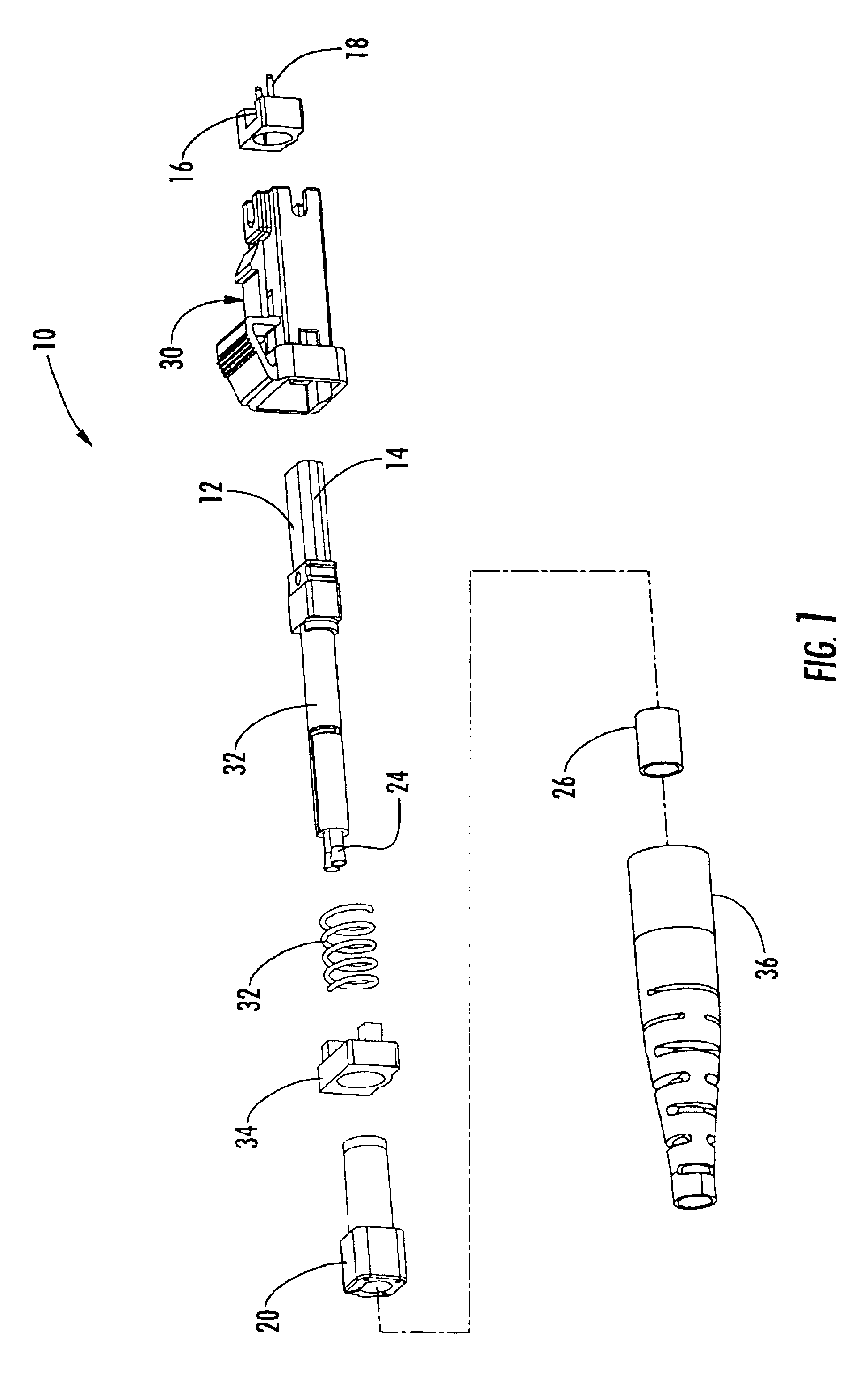
[0030]The present invention now will be described more fully hereinafter with reference to the accompanying drawings, in which preferred embodiments of the invention are shown. This invention may, however, be embodied in many different forms and should not be construed as limited to the embodiments set forth herein; rather, these embodiments are provided so that this disclosure will be thorough and complete, and will fully convey the scope of the invention to those skilled in the art. Like numbers refer to like elements throughout.

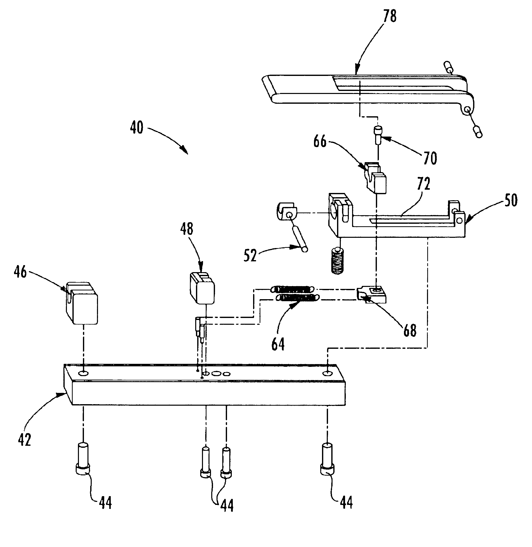
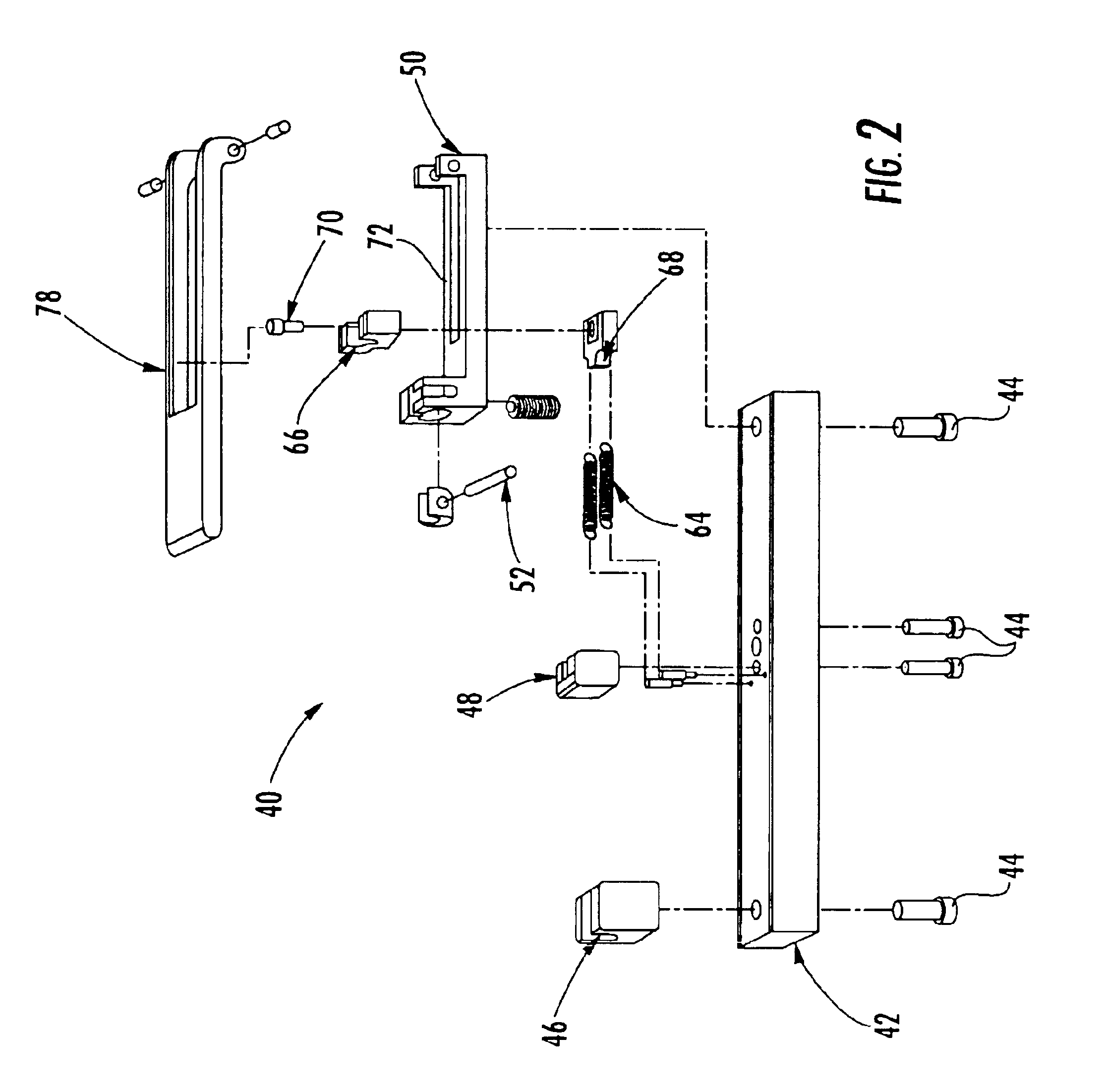
[0031]A method is provided according to the present invention for validating the continuity of one or more optical field fibers with respective optical fiber stubs carried by a fiber optic connector mounted upon end portions of the optical field fibers. While the method of the present invention can be utilized to perform continuity testing following the mounting of a variety of different fiber optic connectors upon the end portions of the optical field fib...


PUM


Abstract

Methods are provided for validating the continuity of one or more optical fibers upon which a fiber optic connector is mounted. Typically, the fiber optic connector is mounted upon an optical field fiber by actuating a cam mechanism to secure the optical field fiber in position relative to an optical fiber stub. If subsequent testing indicates that the continuity of the optical field fiber and the optical fiber stub is unacceptable, the cam mechanism can be deactuated, the optical field fiber can be repositioned and the cam mechanism can be reactuated without having to remove and replace the fiber optic connector. In order to determine if continuity has been established between the optical field fibers and respective optical fiber stubs, a method is also provided that introduces light into at least one of each pair of optical field fibers and optical fiber stubs and that only secures the position of each optical field fiber relative to the respective optical fiber stub once the glow associated with each pair of optical field fibers and optical fiber stubs dissipates, which dissipation indicates the establishment of continuity. An improved multifiber connector and installation tool are also provided to facilitate the establishment and validation of the continuity of optical field fibers and optical fiber stubs in order to reduce the time and cost required to connectorize optical field fibers in the field.

Description

CROSS REFERENCE TO RELATED APPLICATION[0001]This application is a divisional patent application of U.S. patent application Ser. No. 09 / 532,722, filed on Mar. 22, 2000, now U.S. Pat. No. 6,816,661.FIELD OF THE INVENTION[0002]The present invention relates generally to the connectorization of optical fibers and, more particularly, to multifiber connectors, installation tools and associated methods for validating optical fiber continuity during the connectorization process.BACKGROUND OF THE INVENTION[0003]Although fiber optic connectors can generally be most efficiently and reliably mounted upon the end portions of optical fibers in a factory setting during the production of fiber optic cable, many fiber optic connectors must be mounted upon the end portions of optical fibers in the field. As such, a number of fiber optic connectors have been specifically developed to facilitate field installation. One advantageous type of fiber optic connector that is specifically designed to facilitat...

Claims


Application Information

Patent Timeline
Patent Type & Authority Patents(United States)
IPC IPC(8): G02B6/38B05B3/00B05B3/04
CPCG02B6/3807G02B6/3833G02B6/3898G02B6/3846G02B6/3869G02B6/3806G02B6/3885G02B6/3843G02B6/4441G02B6/4457G02B6/4458G02B6/4471G02B6/4477G02B6/4478G02B6/475G02B6/26
Inventor BARNES, BRANDON A.CHURCH, THOMAS A.DE JONG, MICHAELGIEBEL, MARKUS A.KERR, SEAN M.
Owner CORNING OPTICAL COMM LLC
Learn More