Failure isolation in a distributed processing system employing relative location information

a technology of relative location and failure isolation, applied in the field of distributed processing systems, can solve the problems of difficult failure isolation, high cost of failure isolation, and diagnostic routines that can only locate “hard” failures

Inactive Publication Date: 2005-08-16
INTELLECTUAL DISCOVERY INC
View PDF22 Cites 28 Cited by
  • Summary
  • Abstract
  • Description
  • Claims
  • Application Information

AI Technical Summary

Benefits of technology

[0011]As the result, a user is able to examine the local error indicators and isolate the access failure, and to conduct repairs without a requirement for external diagnostics.
[0012]Alternatively, an error message representing the identifier is posted to an error log; and, subsequently, the posted error messages of the plurality of processor nodes may be accumulated. Thus, the accumulated error messages may be analyzed at a convenient time, allowing the user to isolate and repair multiple intermittent failures.

Problems solved by technology

In a system having a plurality of processor nodes, it becomes difficult to isolate failures.
As pointed out, e.g., by U.S. Pat. No. 6,031,819, a failure detector and alarm may be provided at each node of a system to detect and isolate a failure, with the result that failure isolation is expensive.
Such diagnostic routines can only locate “hard” failures, which still occur at the time that the diagnostic routines are being run.
Failures that occur involving communication across a network, such as a multi-drop bus network, may be intermittent, so it is difficult for such diagnostic routines to locate and diagnose the failures.
Diagnosis of such failures therefore requires service cost to bring a trained user with an external processor to the system, to conduct the diagnostics, and to isolate and locate the failures.
The system may be down, or may be unreliable, for the duration of the time between the first occurrence of a failure and the isolation, location and repair of the failure.

Method used


Image

  • Failure isolation in a distributed processing system employing relative location information
  • Failure isolation in a distributed processing system employing relative location information
  • Failure isolation in a distributed processing system employing relative location information

Examples


Embodiment Construction

[0021]This invention is described in preferred embodiments in the following description with reference to the Figures, in which like numbers represent the same or similar elements. While this invention is described in terms of the best mode for achieving this invention's objectives, it will be appreciated by those skilled in the art that variations may be accomplished in view of these teachings without deviating from the spirit or scope of the invention.

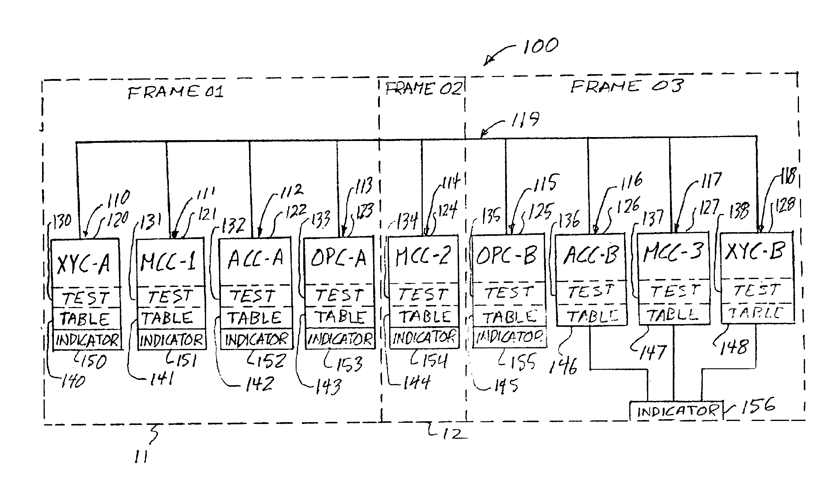
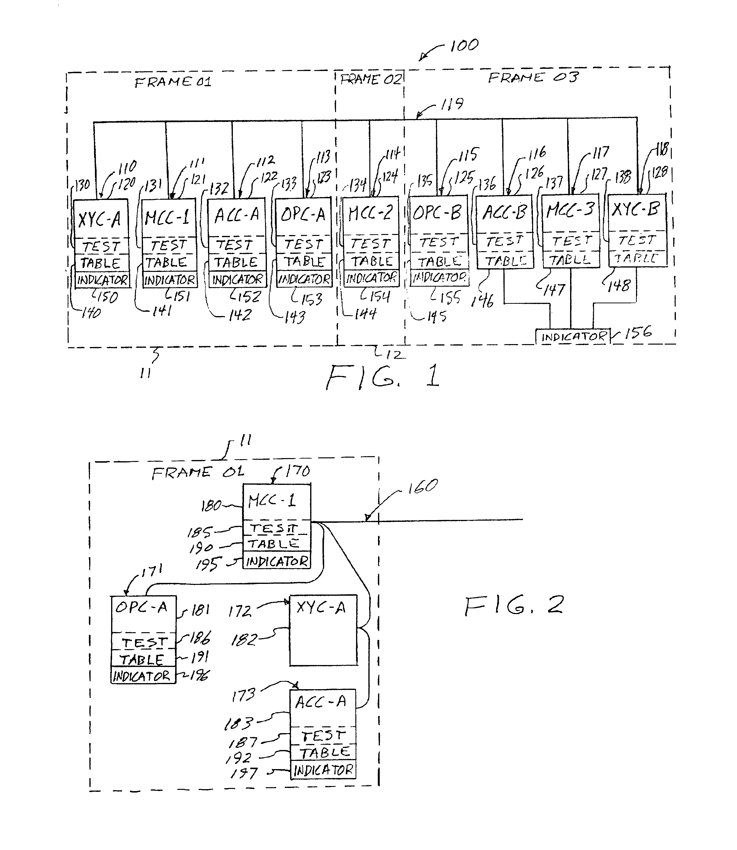
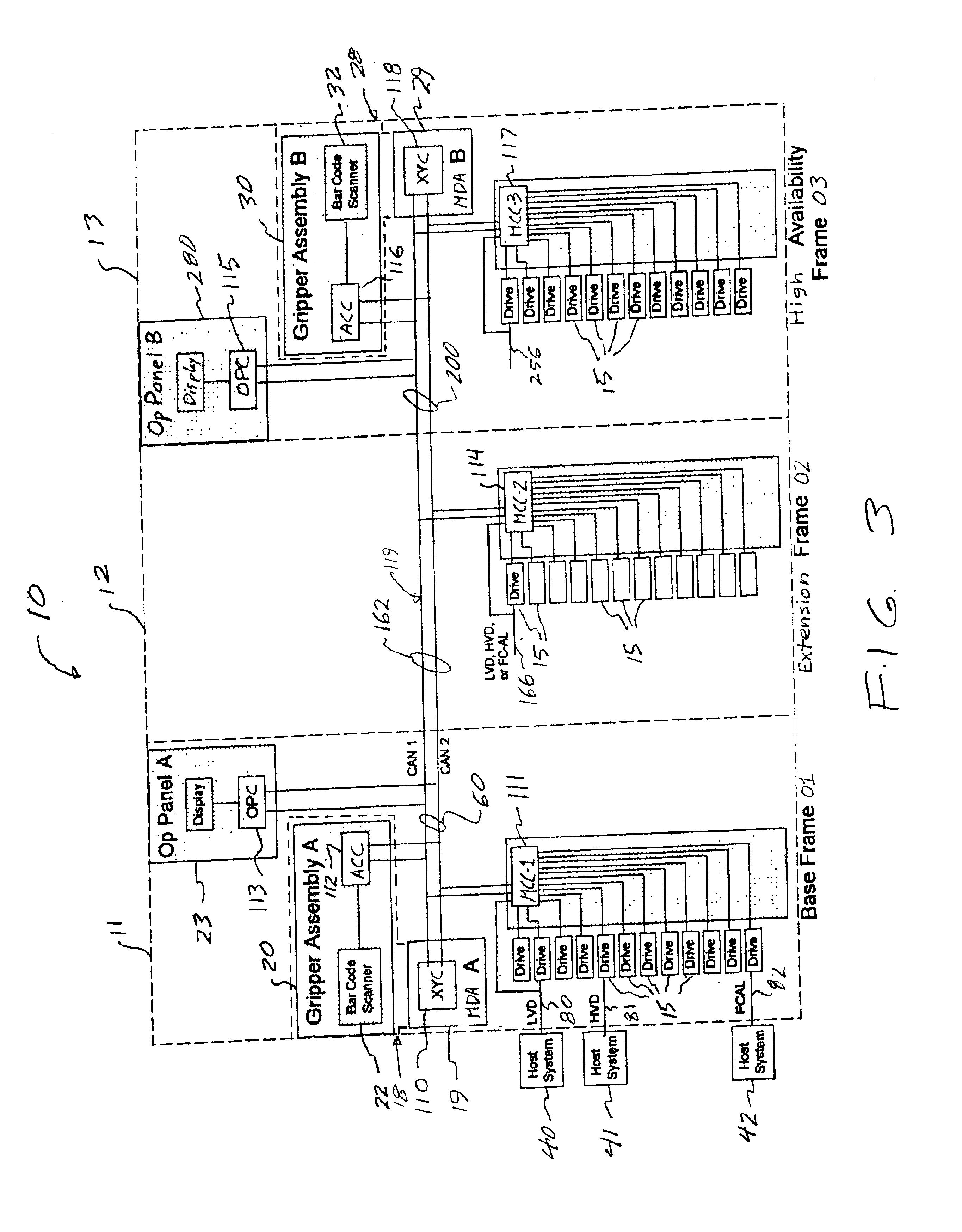
[0022]Referring to FIG. 1, an embodiment of a distributed processing system 100 is illustrated comprising processor nodes 110-118 coupled by a multi-drop bus network 119. Examples of multi-drop bus networks are a CAN bus network, twin lead Ethernet network, or SCSI network, as are known to those of skill in the art. As is also known to those of skill in the art, the multi-drop bus network comprises any appropriate cabling, connections, interfaces, code, etc. Herein, a multi-drop network refers to any communication network where a bre...


PUM


Abstract

Failure isolation in a distributed processing system of processor nodes coupled by a multi-drop bus network. The processor nodes have information of relative locations of the processor nodes on the network, and have an associated local error indicator, such as a character display. Each node independently tests access to other nodes on the network, and upon detecting a failure to access one or more nodes, determines, from the relative locations, the node having failed access which is closest. The failure detecting processor posts, at its associated local error indicator, an identifier of the closest failed access node. A user may inspect the local error indicators and thereby isolate the detected failure.

Description

FIELD OF THE INVENTION[0001]This invention relates to distributed processing systems having a plurality of processor nodes, for example, in control systems, and, more particularly, to isolation of failures in distributed processing systems having a plurality of processor nodes coupled by a multi-drop bus network.BACKGROUND OF THE INVENTION[0002]In a system having a plurality of processor nodes, it becomes difficult to isolate failures. As pointed out, e.g., by U.S. Pat. No. 6,031,819, a failure detector and alarm may be provided at each node of a system to detect and isolate a failure, with the result that failure isolation is expensive. An alternative method is to provide a detailed map of the system and provide specific diagnostic routines to run on the system, but may require an external device such as a laptop, with special purpose software or hardware to communicate with the specific processors and aid in the diagnosis. In a distributed control system, such as is employed in an...

Claims


Application Information

Patent Timeline
Patent Type & Authority Patents(United States)
IPC IPC(8): H04L1/22
CPCH04L1/22
Inventor GOODMAN, BRIAN GERARDMCINTOSH, MICHAEL PHILIPROBERTS, ROBIN DANIEL
Owner INTELLECTUAL DISCOVERY INC
Why Eureka
Try Eureka