Utility distribution system

Inactive Publication Date: 2005-08-23
STEELCASE INC
View PDF210 Cites 79 Cited by
  • Summary
  • Abstract
  • Description
  • Claims
  • Application Information

AI Technical Summary

Problems solved by technology

Typically, such known arrangements are not optimally suited for use in a dynamic work environment, where individual and team spaces are ideally capable of rapid configuration and reconfiguration by the workers themselves in a highly efficient manner, as needed for varied sets of individual or group activities.
However, known arrangement for the display of information in any work environment, which typically utilize both vertical surfaces and horizontal surfaces provided within the work environment, do not fully achieve this or other purposes that are desirable.
However, because the amount of vertical wall surfaces available for use to display information is limited, the volume of information that can be displayed is limited.
Moreover, fixed walls are not readily reconfigurable to form work areas since reconfiguration of the work space is generally a time-consuming and labor-intensive

Method used


Image

  • Utility distribution system
  • Utility distribution system
  • Utility distribution system

Examples


Embodiment Construction

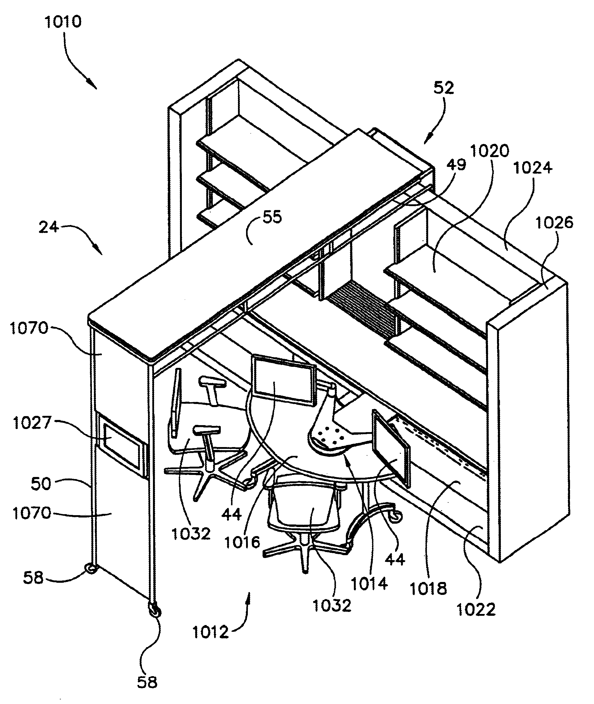
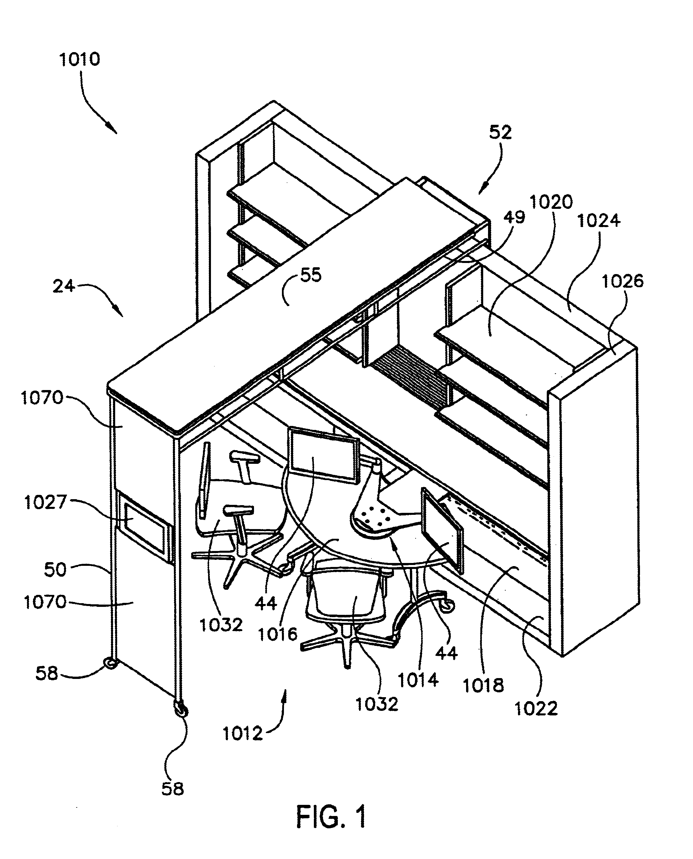
[0077]Referring to FIG. 1, a work space 1010 is shown including a workstation 1012 configurable for use by one or a plurality of workers or other persons. Workstation 1012 includes a movable display support system 1014 along with other articles of furniture shown as an associated mobile worksurface or table 1016, a fixed worksurface 1018, storage units shown as shelving units 1020 and lateral files 1022. Work space 1010 also provides walls shown as partial height partition walls including a base wall 1024 and side walls 1026 as well as a utility distribution system shown as a utility threshold 24 movable on a track 31 (not visible in FIG. 1). According to any preferred embodiment, the utility threshold is of a type disclosed in U.S. patent application Ser. No. 09 / 887,519 titled “MOVABLE DISPLAY SUPPORT SYSTEM” filed Jun. 22, 2001 (the full and entire disclosure of which is hereby incorporated herein by reference), U.S. patent application Ser. No. 09 / 183,023, titled “Workstation” and...


PUM


Abstract

A work environment providing a work area and a workstation including the information display system are also disclosed. A utility distribution system is also disclosed. An information display system is further disclosed. The work environment may provide a work space that can be arranged or divided to include at least one work area within the available floor space. The utility distribution system includes a utility threshold may be adapted for movement along a predefined path about the work area to selectively deliver utilities to at least one portion of the work area. The utility distribution system may be selectively positioned for use in a variety of locations relative to a track system. The information display system may include a track system adapted to attach to a mounting structure and a plurality of display panels coupled to the track system for movement with respect to the mounting structure.

Description

CROSS-REFERENCE TO RELATED APPLICATIONS[0001]The present invention is a division of and claims priority under 35 U.S.C. § 120 from U.S. patent application Ser. No. 09 / 183,023 titled “WORKSTATION” filed Oct. 30, 1998, now U.S. Pat. No. 6,374,547, the full and entire disclosure of which is hereby incorporated herein by reference, and is a division of copending U.S. patent application Ser. No. 09 / 887,519 titled “MOVABLE DISPLAY SUPPORT SYSTEM” filed Jun. 22, 2001, the full and entire disclosure of which is hereby incorporated herein by reference.[0002]The following U.S. patent applications are cited by reference and hereby incorporated herein by reference: (a) Ser. No. 09 / 182,998 titled “INFORMATION DISPLAY SYSTEM” filed Oct. 30, 1998; (b) Ser. No. 09 / 183,021, titled ‘WORK ENVIRONMENT’ and filed on Oct. 30, 1998; (c) Ser. No. 09 / 182,997 titled “DISPLAY BOARD SYSTEM” filed Oct. 30, 1998; (d) Ser. No. 09 / 182,999 titled “DISPLAY BOARD SYSTEM” filed Oct. 30, 1998; (e) U.S. patent applicati...

Claims


Application Information

Patent Timeline
IPC IPC(8): A47B21/03A47B21/00A47B83/00F16M11/04F16M11/00F16M11/42F16M11/02G09F15/00G09F7/08G09F7/02
CPCA47B21/00A47B21/0314A47B83/001F16M11/04F16M11/2014F16M11/2085F16M11/42G09F7/08G09F15/00G09F15/0068
Inventor BALOGA, MARK A.FORSLUND, III, CARL V.FELDPAUSCH, THOMAS G.
Owner STEELCASE INC
Why Eureka
Try Eureka