Power transmission device

Inactive Publication Date: 2005-08-23
NIFCO INC
View PDF5 Cites 18 Cited by
  • Summary
  • Abstract
  • Description
  • Claims
  • Application Information

AI Technical Summary

Benefits of technology

[0015]According to the present invention, in the power transmission device, the two gear assemblies and idle gear are retained in a housing, so that the device is assembled as a unit. Therefore, it is possible to improve handling and installing the device in an applicable driving apparatus. Alternatively, the two gear assemblies and idle g

Problems solved by technology

However, no conventional power transmission mechanism can transmit the drive power in such a manner, and there is no prior art document showing a power transmission device at least with a si

Method used


Image

  • Power transmission device
  • Power transmission device
  • Power transmission device

Examples


Embodiment Construction

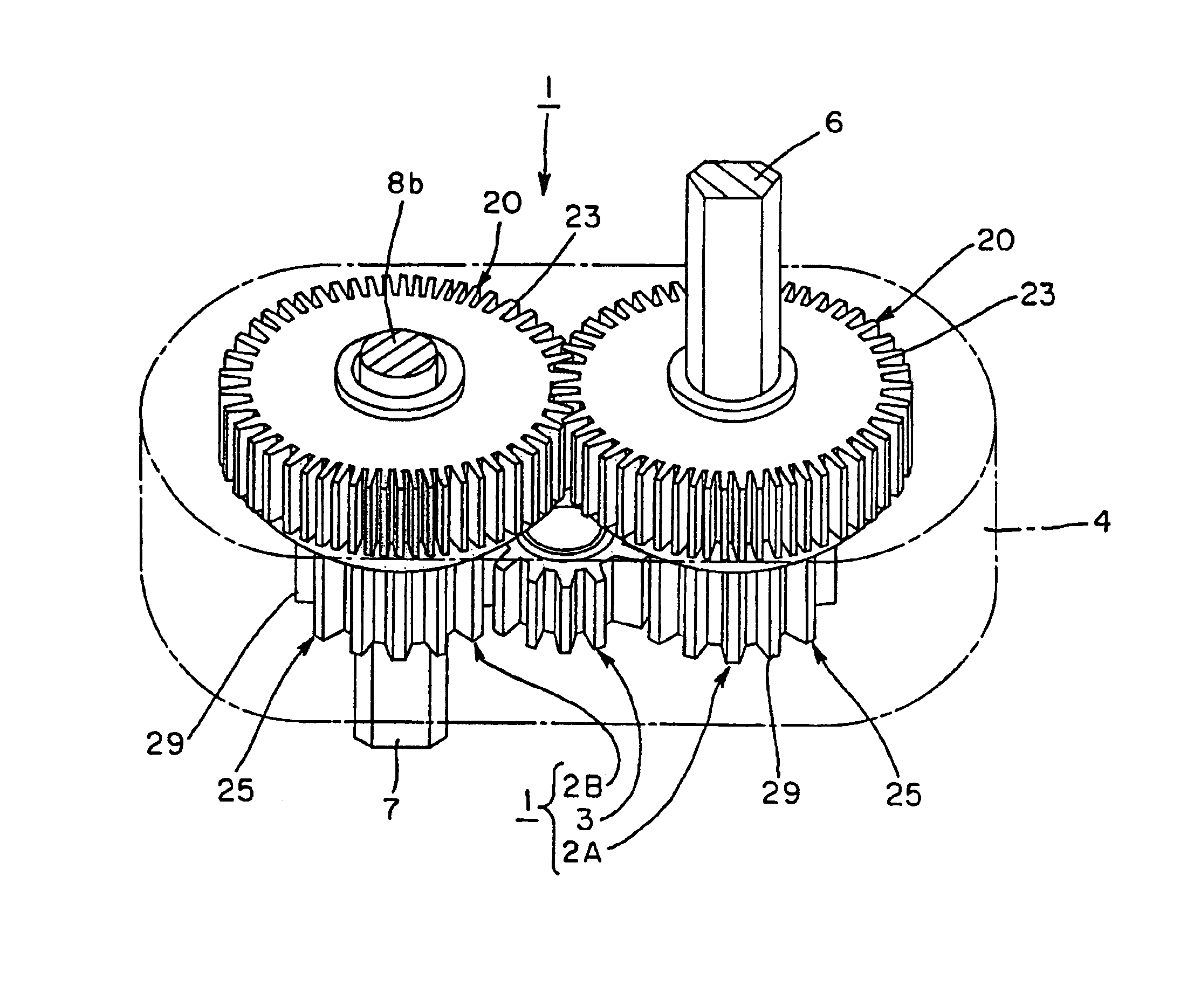
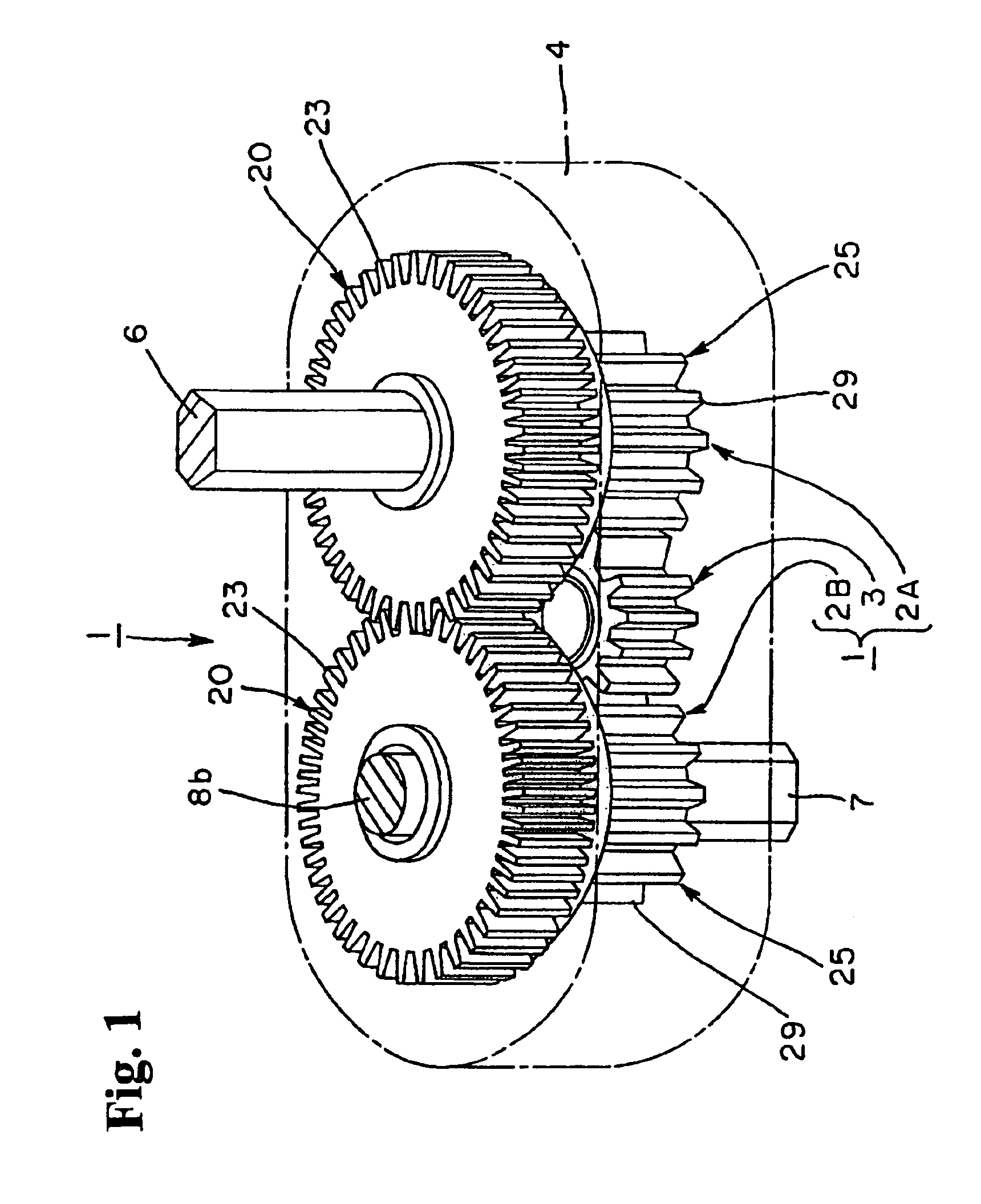
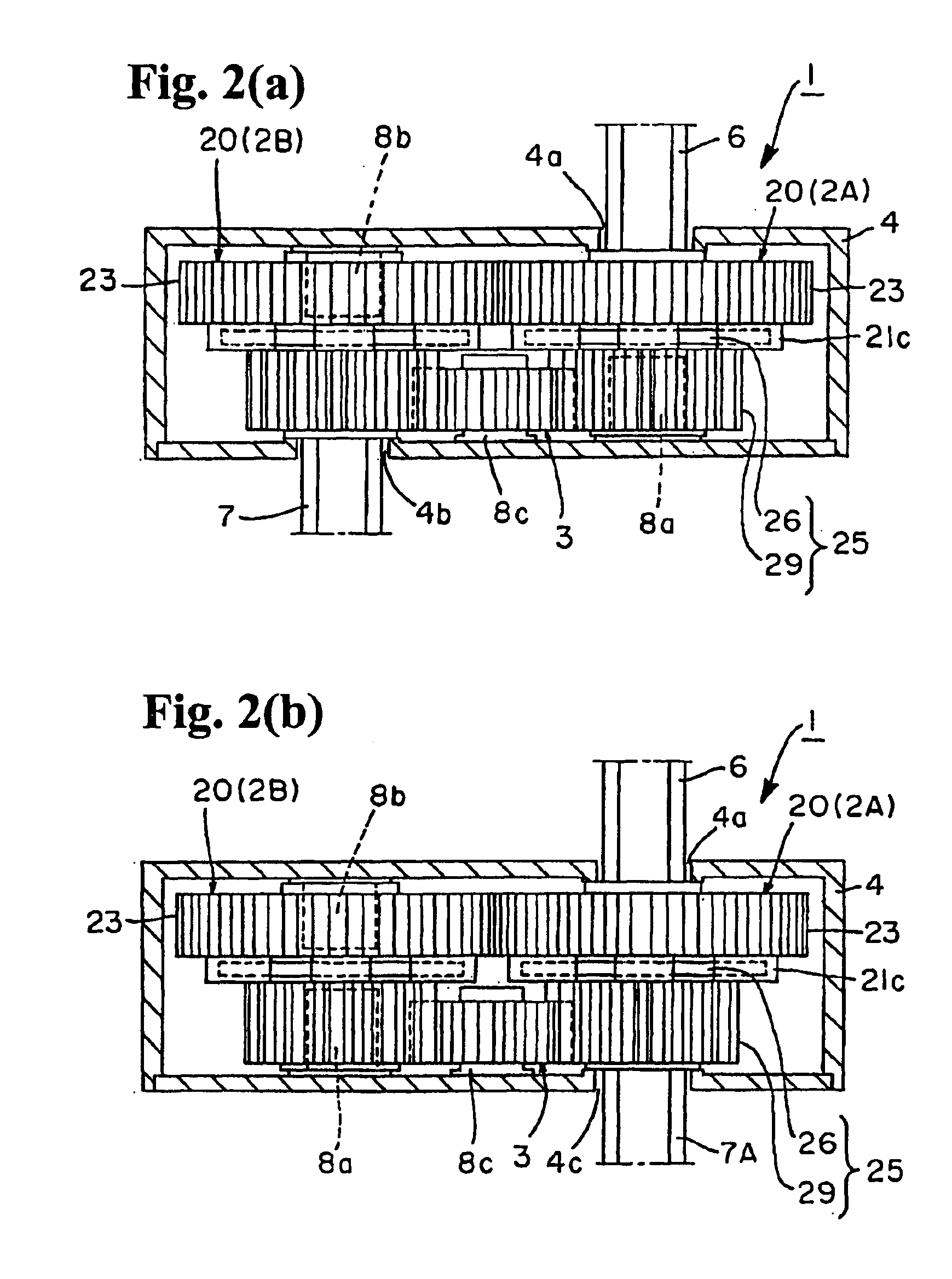
[0026]Hereunder, embodiments of the present invention will be explained with reference to the accompanying drawings. FIG. 1 is a schematic view of a power transmission device. FIGS. 2(a) and 2(b) are cross sectional views showing a structure of the power transmission device. FIG. 3(a) is a partially sectional view showing a structure of the device seen from above, and FIGS. 3(b) and 3(c) are enlarged views showing an operation of a planetary gear. FIGS. 4(a) and 4(b) are views showing the power transmission device seen from an idle gear side.

[0027]FIGS. 5(a) and 5(b) are views showing a first gear constituting a gear assembly of the power transmission device, wherein FIG. 5(a) is a cross sectional view taken along line 5(a)—5(a) in FIG. 5(b), and FIG. 5(b) is a bottom view of the first gear. FIGS. 6(a) and 6(b) are views showing a second gear constituting a gear assembly of the power transmission device, wherein FIG. 6(a) is a top view of the second gear, and FIG. 6(b) is a cross se...


PUM


Abstract

A power transmission device includes a pair of gear assemblies and an idle. Each of the gear assemblies includes a first gear having continuous external teeth on a peripheral wall and a second gear having continuous external teeth on a peripheral wall. The first gear and second gear are arranged to form a one-way clutch. When the first gear rotates in one direction relative to the second gear, the first gear is not connected to the second gear. When the first gear rotates in the other direction relative to the second gear, the first gear is connected to the second gear. The external teeth of the first gears in the gear assemblies engage each other, and the external teeth of the second gears in the gear assemblies engage the idle gear. One direction output at the second gear is obtained regardless of an input direction at the first gear.

Description

BACKGROUND OF THE INVENTION AND RELATED ART STATEMENT[0001]The present invention relates to a power transmission device in which an output shaft always rotates in the same direction when an input shaft is rotated in either forward or reverse direction.[0002]There is a driving device such as a manual pencil sharpener and various types of drilling machines in which a driving unit at an output side is operated when a handle is rotated in one direction (forward rotation) and the driving unit becomes idle or a non-operating state when the handle is rotated in a reverse direction (reverse rotation). In terms of configuration, a device may be provided with a one-way clutch for transmitting a rotational drive of a handle to a driving unit. In such a driving device, from an operational point of view, the operational efficiency can be improved when a driving unit (output side) can rotate in the same direction regardless of the forward rotation or the reverse rotation of a handle (input shaft ...

Claims


Application Information

Patent Timeline
IPC IPC(8): F16H3/00F16H31/00F16H35/00
CPCF16H3/005F16H31/001Y10T74/19205Y10T74/19172Y10T74/19219Y10T74/18368
Inventor JINBO, NAOTO
Owner NIFCO INC
Why Eureka
Try Eureka