Transfer device, transfer device assembly, and accommodating device thereof

a technology of transfer device and assembly, which is applied in the direction of conveyor parts, transportation and packaging, nursing beds, etc., can solve the problems of large power source, difficult task of transferring patients between beds and stretchers, and heavy work

Inactive Publication Date: 2005-08-23
DAIHEN CORP
View PDF9 Cites 49 Cited by
  • Summary
  • Abstract
  • Description
  • Claims
  • Application Information

AI Technical Summary

Benefits of technology

[0011]The present invention has been proposed under the circumstances described above. It is, therefore, an object of the present invention to provide ...

Problems solved by technology

However, this task is heavy work and requires considerable manpower.
For these reasons, the task of transferring a patient between bed and stretcher is very difficult.
There is therefore the problem that a ...

Method used


Image

  • Transfer device, transfer device assembly, and accommodating device thereof
  • Transfer device, transfer device assembly, and accommodating device thereof
  • Transfer device, transfer device assembly, and accommodating device thereof

Examples


Embodiment Construction

[0042]Preferred embodiments of the present invention will be described below with reference to the accompanying drawings.

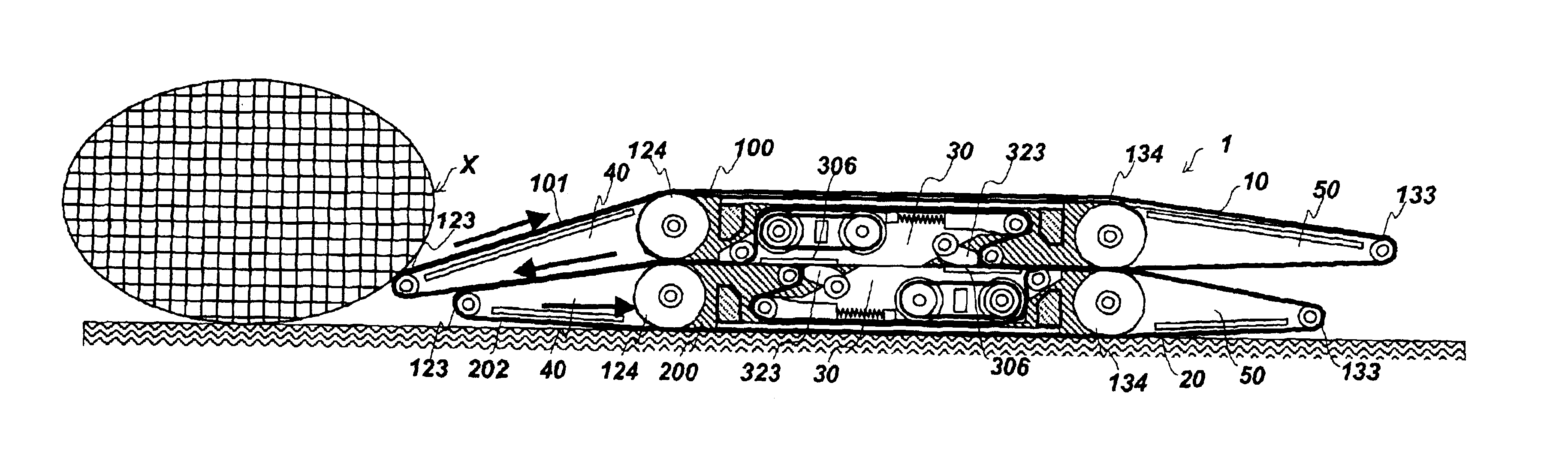
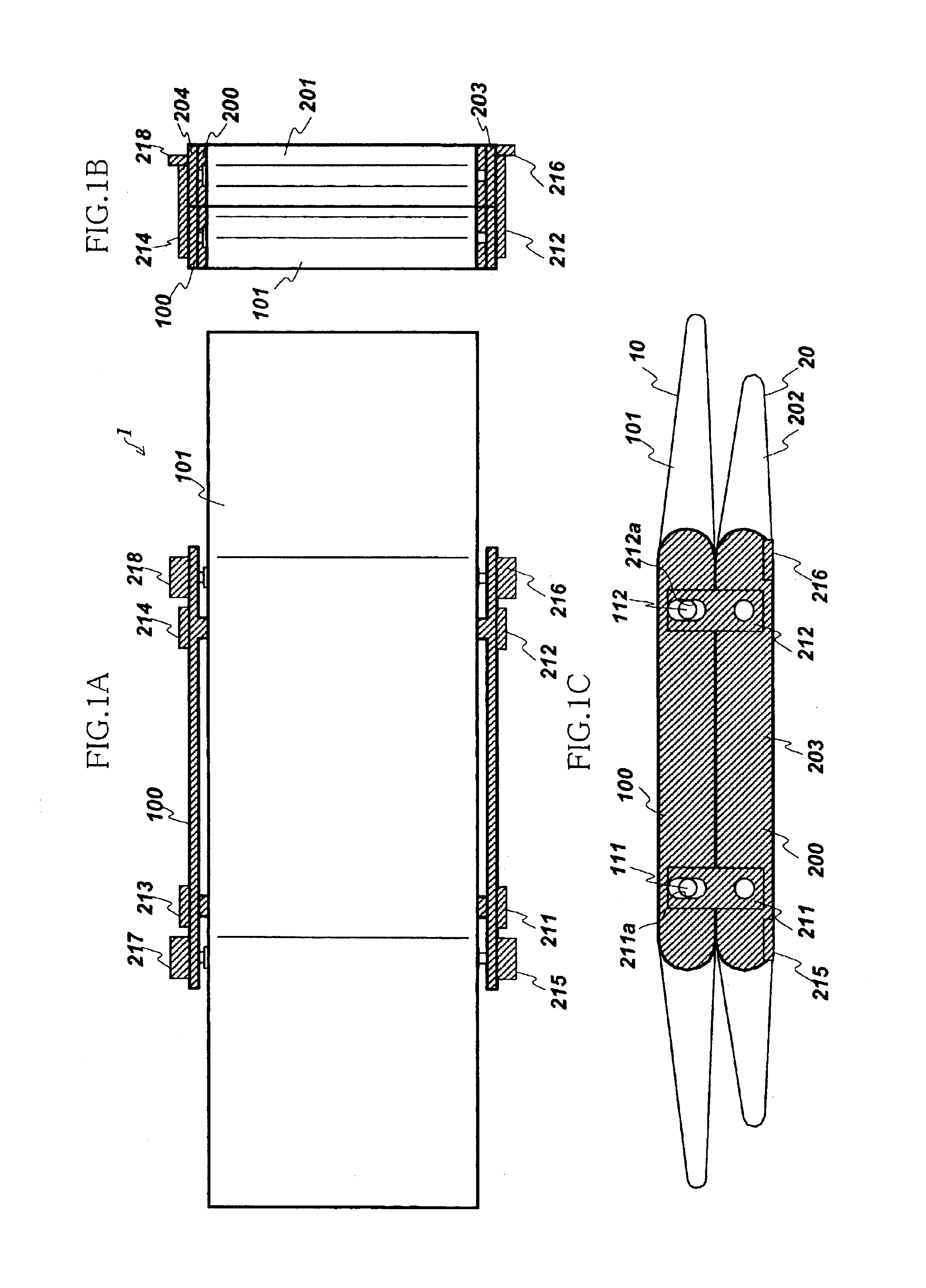
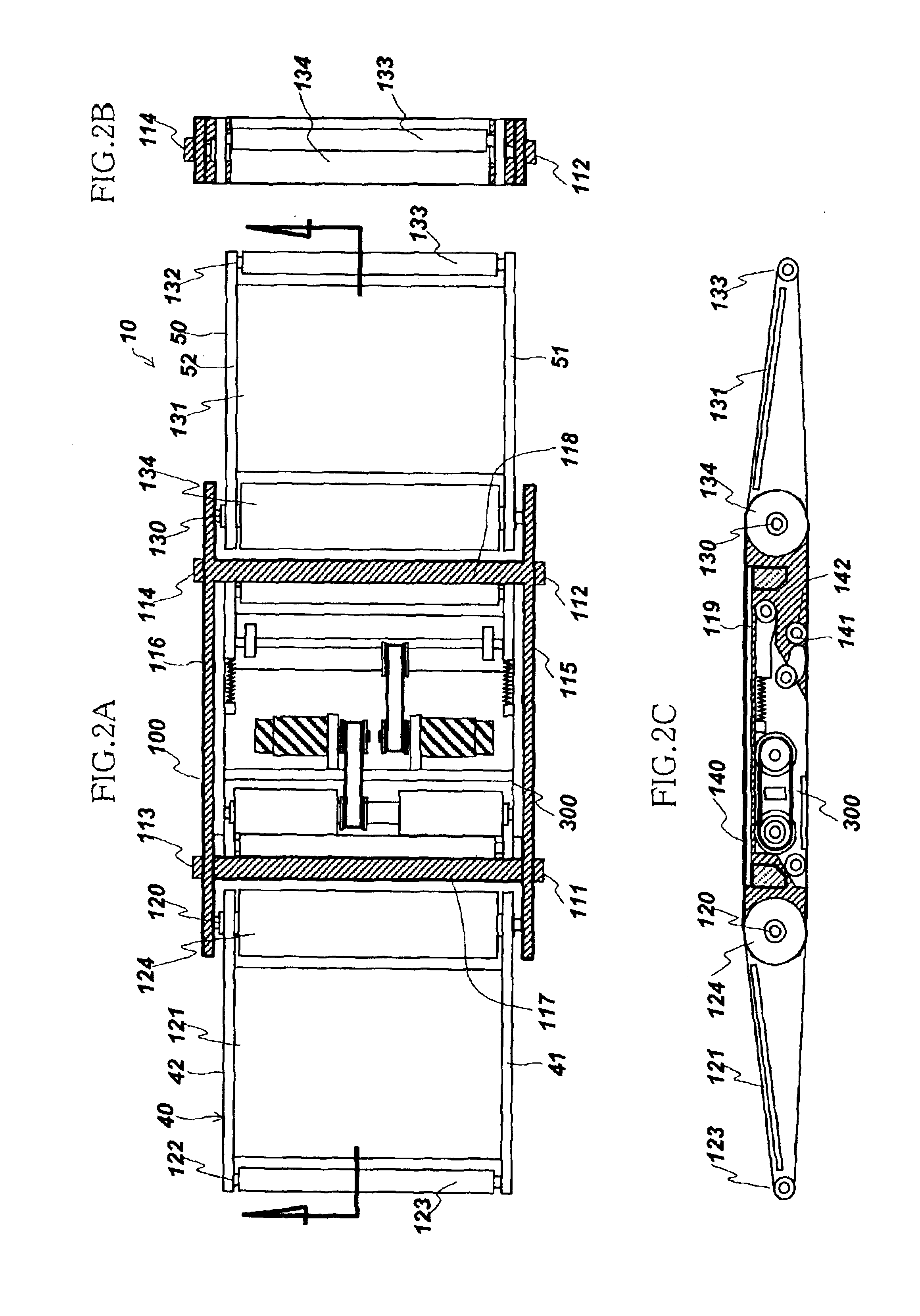
[0043]Referring to FIGS. 1 to 6, the basic construction of an embodiment of a transfer device 1 according to the present invention will be described. FIG. 1 show the external appearance of the transfer device 1, where FIG. 1A is a plan view, FIG. 1B a front view and FIG. 1C a side view of the device. As can be seen from these figures, the transfer device 1 is assembled in a configuration in which an upper mechanism 10 and a lower mechanism 20 are superimposed in the vertical direction. FIG. 2 show the condition with the belt of the upper mechanism 10 removed, where FIG. 2A is a plan view, FIG. 2B a front view and FIG. 2C a central longitudinal cross-sectional view. FIG. 3 is a plan view shown with the drive section 30 shown in FIG. 2 extracted. FIG. 4 is a central longitudinal cross-sectional view thereof. Also, FIGS. 5A and 5B show the procedure for mounting the ...


PUM


Abstract

A transfer device includes an upper mechanism and a lower mechanism associated with the upper mechanism. The upper mechanism includes a first endless belt that circulates in forward and reverse directions. The lower mechanism includes a second endless belt that circulates in forward and reverse directions independently of the first endless belt. The first and the second endless belts are selectively brought into and out of engagement with each other.

Description

BACKGROUND OF THE INVENTION[0001]1. Field of the Invention[0002]The present invention relates to a transfer device, transfer device assembly and accommodating device thereof suitable for use in transferring patients between beds and stretchers, for example.[0003]2. Description of the Related Art[0004]For transferring patients who are in a condition in which they cannot walk or in a condition in which walking is difficult within a hospital, a transfer platform called a stretcher is employed. A stretcher is constituted by a loading platform having sufficient width and length required for carrying a patient, that is supported on the feet fitted with castors, at practically the same height as the surface of a bed. The stretcher is brought up next to the bed and the patient is transferred between the bed and the stretcher.[0005]This transfer of a patient is usually performed by lifting the patient by a plurality of persons pulling up the edges of the sheet. However, this task is heavy wo...

Claims


Application Information

Patent Timeline
IPC IPC(8): A61G7/10A61G1/00B65G15/12A61G7/14B65G7/02B65G21/12
CPCA61G7/1032A61G7/1046A61G7/1074A61G2200/32
Inventor KASAGAMI, FUMIOHOJO, FUMIO
Owner DAIHEN CORP
Why Eureka
Try Eureka