Irradiation unit

a technology of light-emitting units and leds, which is applied in the direction of boring tools, dental prosthetics, dental tools, etc., can solve the problems of increasing the weight of the unit, substantial radiation losses, and the predominant portion of the light emitted by the leds cannot be used to illuminate the treatment surface, so as to improve the light power, faster and more reliable light-induced hardening of dental filling materials, and the effect of improving the light power

Inactive Publication Date: 2005-08-23
3M ESPE
View PDF26 Cites 55 Cited by
  • Summary
  • Abstract
  • Description
  • Claims
  • Application Information

AI Technical Summary

Benefits of technology

[0012]Consequently, it is an object of the present invention to provide an irradiation unit with improved light power with the aid of which it is possible, for example, to achieve quicker and more reliable light-induced hardening of dental filling materials which is quicker and more reliable.

Problems solved by technology

Apart from the fact that such conical optical conductor members such as have been described in the above publications, or else in WO 99 / 16136 (FIG. 4), are expensive to produce, and increase the weight of the unit, they also cause substantial radiation losses.
Consequently, the predominant portion of the light emitted by the LEDs cannot be used to illuminate the treatment surface, since the luminous cones with the aid of which LEDs emit light usually have usually have substantially larger aperture angles.
In addition, the fabrication of the multiply conical optical conductor is, once again, more complicated and more expensive.
There are also other designs of irradiation units based on LED that manage without a conical optical conductor member and the disadvantages associated therewith.
A substantial fraction of the beams cannot be guided by the positive lens onto the light entrance orifice, and is therefore lost for the irradiation of the treatment site.
This is to be ascribed to inadequate light power as a consequence of non-optimum launching of light, as well as of the small number of the LEDs that can be used with the arrangement described.
The conical optical conductor also has the problems already described above.
A further disadvantage caused by the high operating currents is that disproportionately high heat occurs at the LEDs, as a result of which the unit becomes hot after a short time, and cannot be used for a prolonged period of time until it has cooled down.
In addition, the service life of LEDs suffers under the high operating currents, resulting in a continuous drop in light power over time.
The individual elements heat one another up, resulting in setting limits for the light intensity and / or the service life.
In addition, the production of such arrangements is substantially more complicated and expensive, since it is not possible to resort to standard components which can be handled effectively in mechanical terms.

Method used


Image

  • Irradiation unit
  • Irradiation unit

Examples


Embodiment Construction

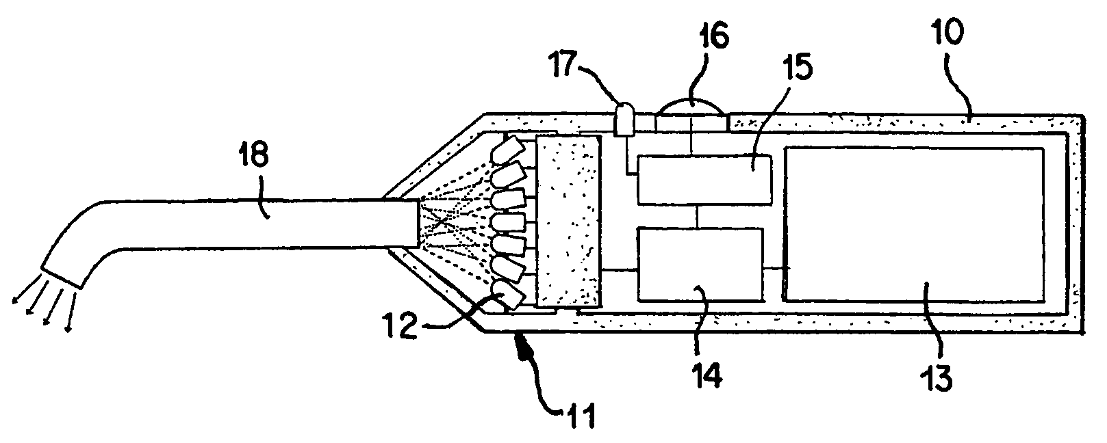
[0049]The hand-held unit, shown in FIG. 1, for irradiating dental plastics includes in the front region of a substantially cylindrical housing (10) a light-emitting unit (11) in the form of an array, for example, fifty, individual light-emitting elements (12), such as light-emitting diodes, which can also be laser diodes.

[0050]The light-emitting elements (12) are fed from a battery (13), arranged in the rear part of the housing (10), via a driver stage (14) that is time-controlled by a control circuit (15). The control circuit (15) is connected to a closing push-button (16) arranged on the side of he housing (10), and to a display diode (17) likewise arranged on the side of the housing (10). Projecting from the front conical end of the housing (10) is a light-conducting unit (18) in the form of an optical fiber rod curved at its front end.

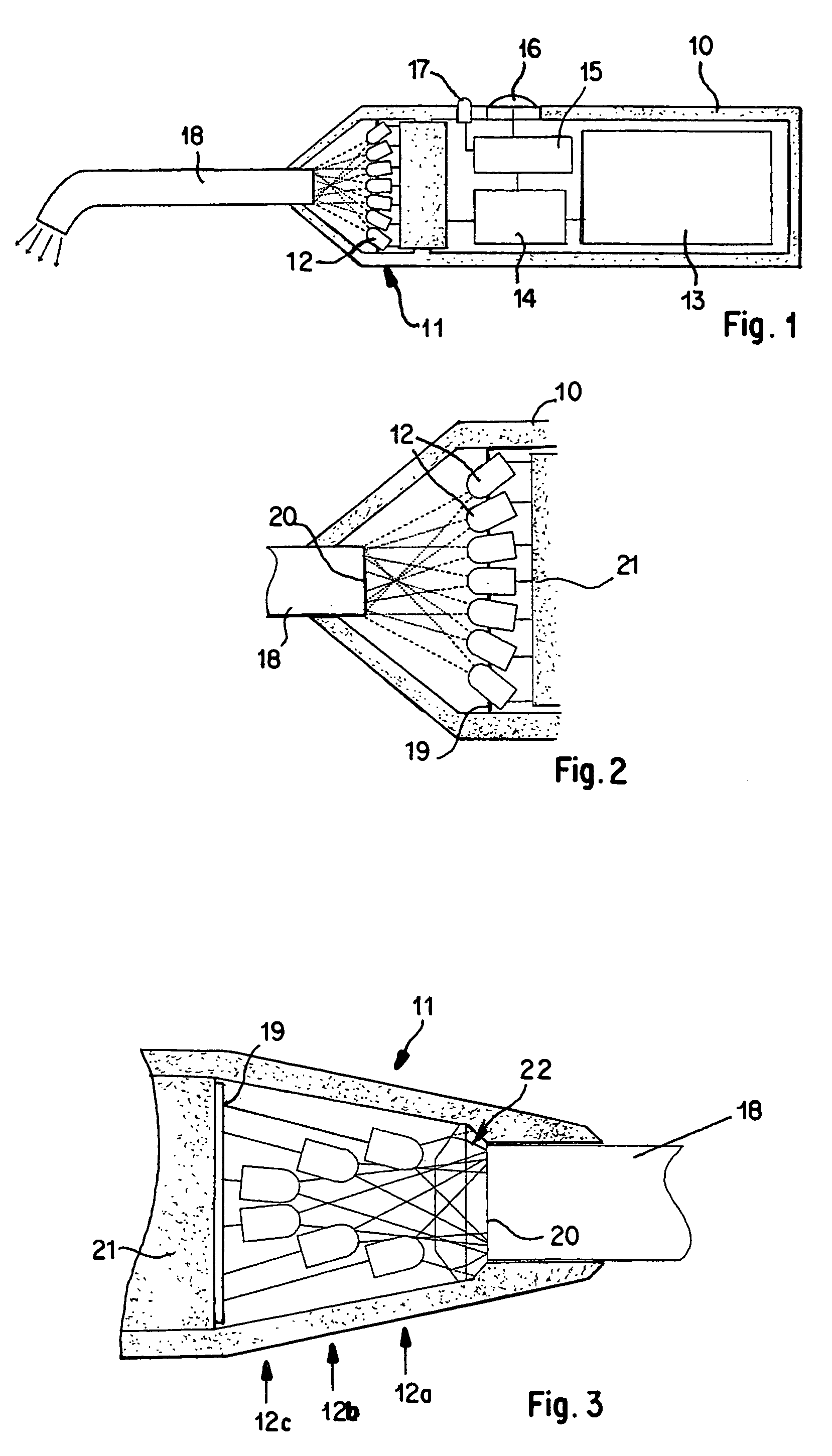
[0051]The light-emitting elements (12) are arranged in this embodiment in a flat holding plate (19) in such a way that their optical axes cut one ...


PUM


Abstract

The radiation device has an array (11) of light-emitting diodes (12) providing light beams which are directed onto a focus region (20) at the input end of a light conductor (18), used for directing a focused light beam onto the radiation point. The light-emitting diodes are supported in a planar holder (19) at different inclination angles, for providing a light cone illuminating the light conductor input end from their output beams.

Description

FIELD OF INVENTION[0001]The invention relates to an irradiation unit of high light power, comprising a light-emitting unit, preferably LEDs, and a light-guiding unit with a light-absorbing region such as a fiber-optic optical conductor, which is preferably used in the field of medicine.BACKGROUND OF THE INVENTION[0002]JP-A-9-10238 discloses a dental irradiation unit in which an array of light-emitting diodes is arranged on he hemispherical surface of an optical conductor member, in the shape of a conical sector, made from quartz or plastic, the tip of which merges into a rigid optical fiber rod. The beams of the light-emitting diodes are focused by the optical conductor member by reflection at the conical wall and passed into the rigid optical fiber rod.[0003]WO-97 / 36552 discloses a further dental irradiation unit in which a planar array of light-emitting diodes with parallel optical axes is situated opposite the curved entrance surface of a likewise conical optical conductor member...

Claims


Application Information

Patent Timeline
Patent Type & Authority Patents(United States)
IPC IPC(8): A61C13/15A61C13/00A61N5/06G21K5/00
CPCA61C19/004A61N2005/0652Y10S362/80Y10S362/804A61C2204/002
Inventor HARTUNG, MARTIN
Owner 3M ESPE
Why Eureka
Try Eureka